V. 1.0 | LPKF Laser & Electronics AG
Defining the material settings
1. Mount the material onto the processing table if not already done. For more
information on mounting and fastening the material refer to page 53.
2. Click on [OK].
The phase MaterialSettings is started.
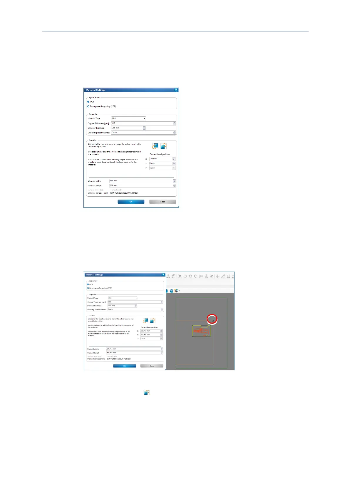
Fig. 38: Material settings
3. Enter the correct values for the material used in the dialog Material settings.
In the group Application, the material PCB is selected as default.
4. Edit the values for the copper layer thickness and material thickness if necessary.
5. For defining the material area, move the dialog Material settings to the side.
6. In the Machining view click on the position of the screen that represents the right
rear corner of your material:
Fig. 39: Defining the right rear corner
The processing head moves to the right rear corner.
7. Click on the button in the dialog Material settings.
The material area is adapted.
8. Click on the position of the screen that represents the front left corner of your
material: