3 Installation – Panel Mount
12
CURRENT OUTPUT CONNECTIONS
The MOD53 can be supplied with up to 2 current outputs designated A and B. It is
shipped with links across the relevant current output pins if the option is fitted. If a
current output is required, remove the link and replace with a cable terminated by a
load resistance not exceeding 1000Ω. For best noise immunity, use a screened
twisted pair cable, with the screen connected to Earth at one end. Use a
sufficiently large cable to avoid a high resistance in the overall current loop. When
either of the outputs is open circuit, in a dual output unit, the other will
indicate a fault by transmitting a 2mA signal. This will be accompanied by a
flashing error message on the Display (E41, see Appendix I)
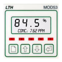
SET POINT RELAY CONNECTIONS
The relay contacts are connected to the terminals only and are electrically isolated
from the instrument itself. They must be connected in series with a 5 Amp
fuse.
MOD53
Load A
Neutral
Live
Neutral
Load B
5A
Figure 5 : Relay contact connection
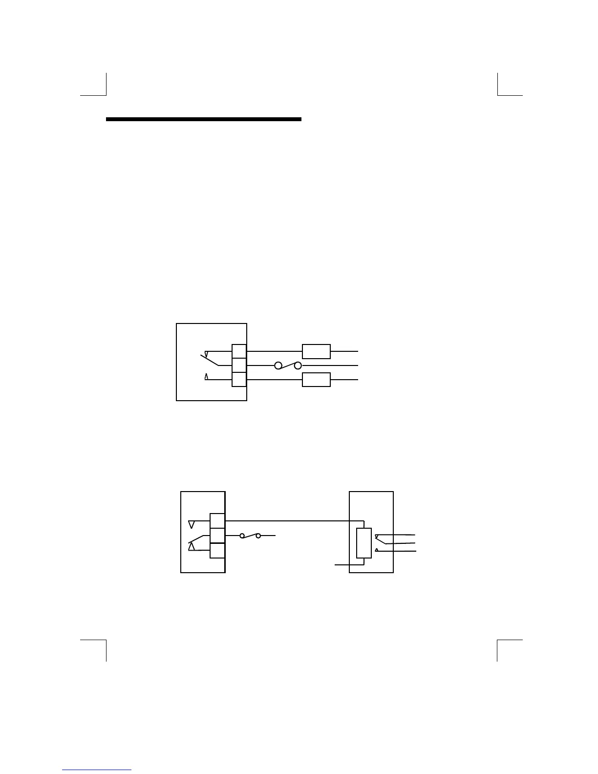
A contact arc suppressor may be required to prevent excessive electrical noise,
depending upon the load. To switch more than 5 Amps will require a slave relay.
MOD53
Slave Relay
Neutral
Live
Figure 6 : Slave relay connection