4 Installation – Surface Mount
21
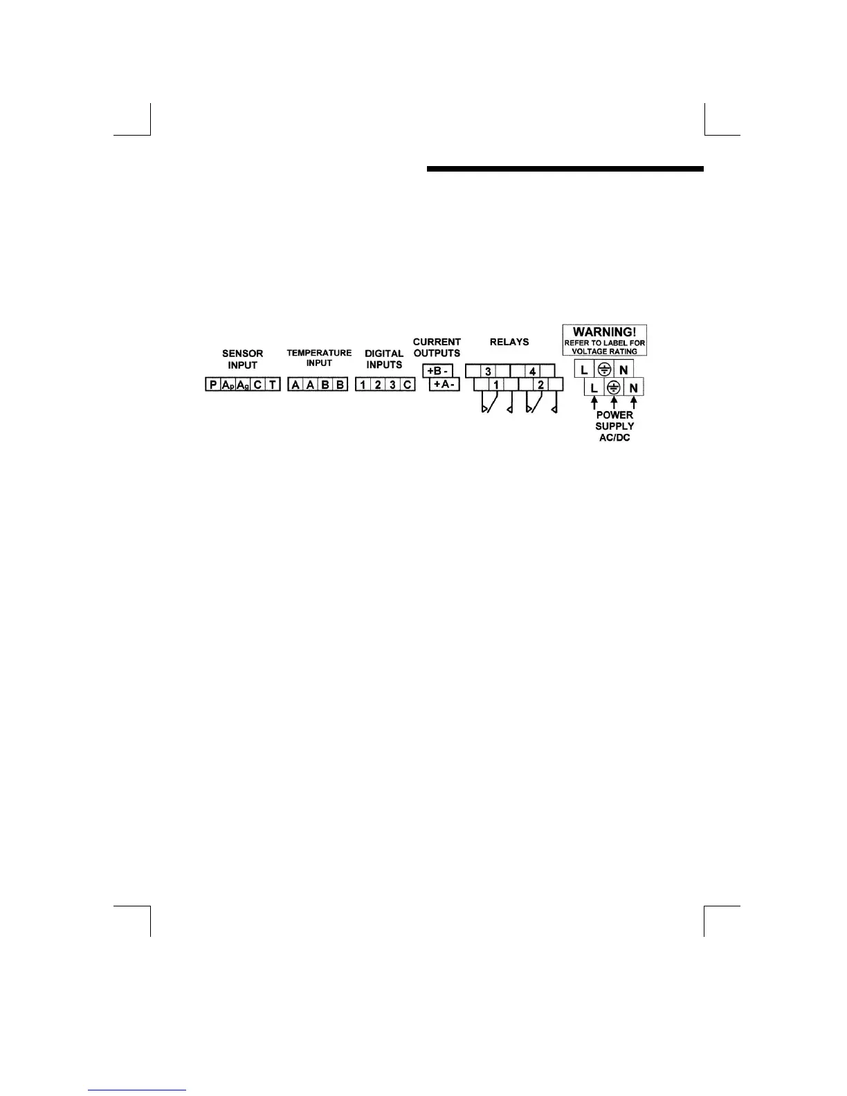
TERMINAL CONNECTIONS
Having ensured that the main power is isolated from the unit, remove the terminal
cover by releasing the screws at each corner. (The terminal cover is the small
cover at the bottom of the front panel. Once the cover has been removed the
following terminal arrangement should be visible. Some terminals may not be fitted
due to different supplied options.
Figure 18 : Surface mount unit, terminal connections
The cables should be fed through the cable glands. After each cable has been
attached, pull most of the cable slack back through the cable gland to prevent any
unwanted RF energy from being radiated inside the housing. Make sure not to
strain the cable within the instrument. Tighten the cable gland onto the cable so
that it grips sufficiently to seal and to prevent the cable from being pulled back
through the gland.
SUPPLY VOLTAGE CONNECTIONS
The MOD53 can be powered from either an AC or DC supply voltage. The unit
provides two terminals for each of the input connections (“Live” & “Neutral” for an
AC input, or + & - for a DC Input), plus an “Earth” terminal. This allows the supply to
be “daisy chained” to the relay contacts and/or other instruments. The instrument
uses a universal power supply that accepts a wide range of voltage and frequency
inputs. Refer to the label adjacent to the power supply terminals for the input
voltage limits. Exceeding these limits may damage the instrument.