Do you have a question about the LTH MOD53 and is the answer not in the manual?
Details the warranty period and terms for the MOD53 instrument.
Describes the MOD53 as a microprocessor-controlled dissolved oxygen monitor.
Lists technical specifications including sensor input, ranges, and compensation.
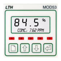
Explains the LCD display, buttons, and status LEDs.
Provides essential safety and EMC guidelines for wiring the unit.
Specifies dimensions and sealing for panel mounting.
Illustrates wiring for different sensor types (OE15, ProcessProbe).
Wiring diagrams for sensors and connection types.
Details the LCD display, programming buttons, and their functions.
Describes how error messages are displayed and managed.
Sets display units (% Sat, ppm, etc.) and probe type (Galvanic, Polargraphic).
Defines the input source and trigger condition for set points.
Configures set point levels, operating modes, and alarm timers.
Navigates the menu to configure current output settings.
Sets the output range (0-20mA or 4-20mA) and adjusts zero/span.
Sets the unit to On-Line/Off-Line mode and controls calibration access.
Guides through zero and span calibration for the DO sensor.
Details the procedure for calibrating the temperature input.
Explains how to calibrate the 4-20mA pressure input.
Guides on adjusting and calibrating the current output signal.
Configures pressure input mode, units, and 4/20mA levels.
Troubleshooting for dead instrument and incorrect access codes.
Diagnosing sensor reading errors and connection problems.
Troubleshooting current output and pressure input issues.
Provides detailed steps for zero and span calibration.
Lists and explains errors detected during instrument startup.
Details errors related to sensor input signals and compensation.
Lists errors concerning current output and pressure input functionalities.
| Resolution | 1920 x 1080 (Full HD) |
|---|---|
| Panel Type | IPS |
| Refresh Rate | 75Hz |
| Brightness | 250 cd/m² |
| Contrast Ratio | 1000:1 |
| Input Ports | HDMI, VGA |
| VESA Mount | 100 x 100 mm |
| Response Time | 5ms |
| Viewing Angle | 178° (H) / 178° (V) |
| Built-in Speakers | Yes |