Contents
3
Contents
Preface..................................................................................................................1
Contents ...............................................................................................................3
1 Introduction.....................................................................................................5
About the MOD53 ............................................................................................5
Unit Specification .............................................................................................5
2 Installation – Safety & EMC............................................................................7
Wiring Installation ............................................................................................7
3 Installation – Panel Mount .............................................................................9
Top Connector ...............................................................................................11
Supply Voltage Connections..........................................................................11
Current Output Connections ..........................................................................12
Set Point Relay Connections .........................................................................12
Set Point Relays 3 & 4 Connection ................................................................13
Bottom Connector ..........................................................................................14
Sensor Input Connections..............................................................................14
Sensor Types.................................................................................................15
Temperature Input Connections.....................................................................16
Pressure Transmitter Input.............................................................................17
RC2 Cleaner Connection ...............................................................................17
Digital Inputs ..................................................................................................18
4 Installation – Surface Mount........................................................................19
Pipe Mounting ................................................................................................20
Terminal Connections ....................................................................................21
Supply Voltage Connections..........................................................................21
Current Output Connections ..........................................................................22
Relay Connections.........................................................................................23
Sensor Input Connections..............................................................................24
Sensor Types.................................................................................................24
Temperature Input Connections.....................................................................26
Pressure Transmitter Input.............................................................................27
RC2 Cleaner Connection ...............................................................................27
Digital Inputs ..................................................................................................28
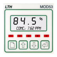
5 User Interface................................................................................................29
The Front Panel .............................................................................................29
The Menu System ..........................................................................................30
Error Messages..............................................................................................30
Access Entry ..................................................................................................30
Unit Configuration ..........................................................................................34
6 Main Display..................................................................................................37
7 Parameters ....................................................................................................41
Units...............................................................................................................43
Sensor Type...................................................................................................44
Temperature Input..........................................................................................44
Salinity............................................................................................................44