3 Installation – Panel Mount
11
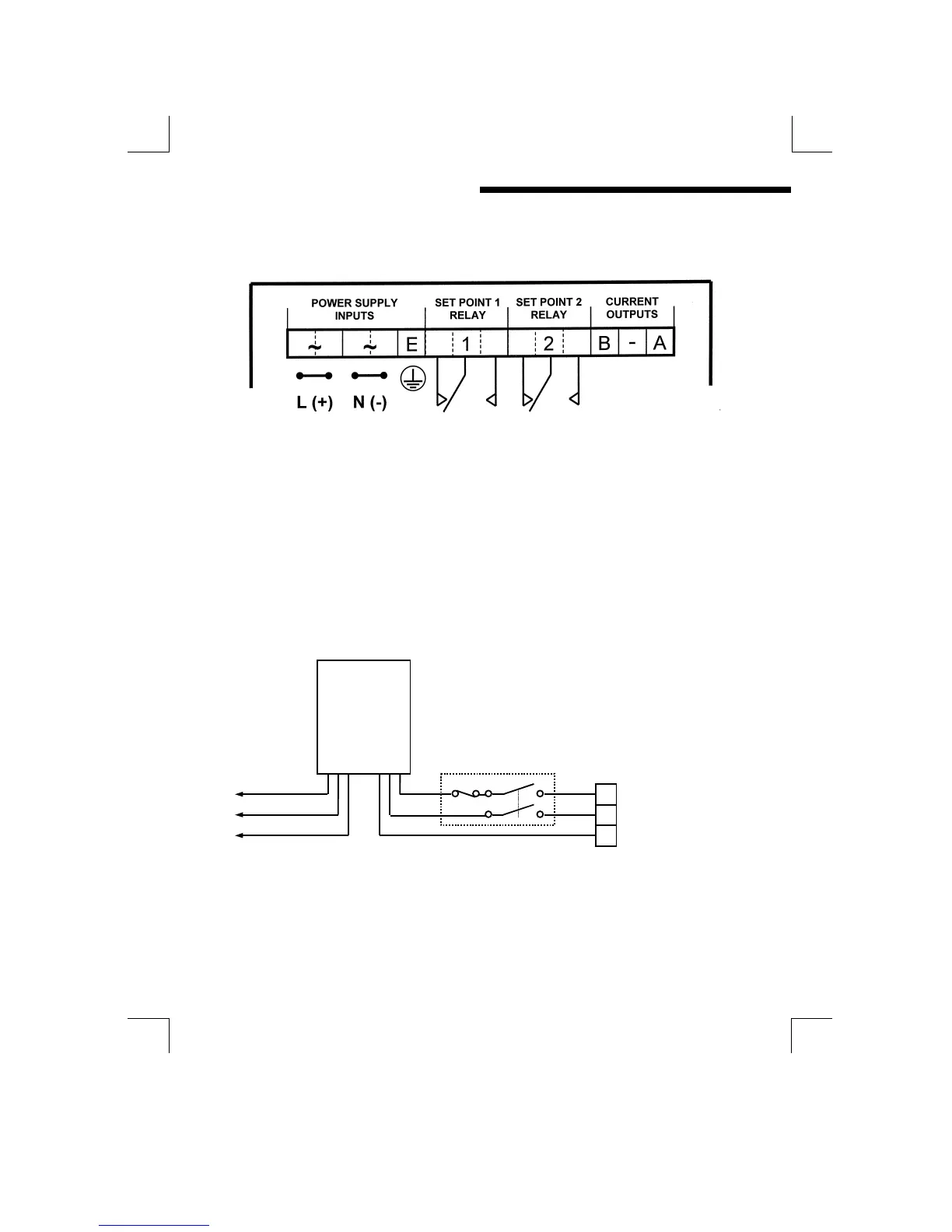
TOP CONNECTOR
Figure 3 : Panel mount unit, top connector wiring
SUPPLY VOLTAGE CONNECTIONS
The MOD53 can be powered from either an AC or DC supply voltage. The unit
provides two terminals for each of the input connections (“Live” & “Neutral” for an
AC input, or + & - for a DC Input), plus an “Earth” terminal. This allows the supply
to be “daisy chained” to the relay contacts and/or other instruments. The
instrument uses a universal power supply that accepts a wide range of voltage and
frequency inputs. Refer to the label adjacent to the power supply terminals for
the input voltage limits. Exceeding these limits may damage the instrument.
Figure 4 : Power supply connection
The power supply should be taken from an isolated spur and fused to a maximum
of 3 Amps. If the relays require greater current, then a separate 5A fuse will be
required. The incoming Earth connection must be connected to the “Earth”
terminal.
MOD53
OUT IN
3A
L
N
E