4 Installation – Surface Mount
22
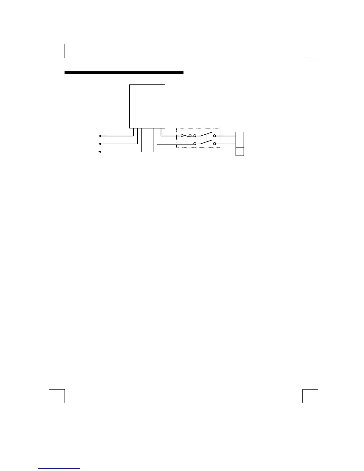
Figure 19 : Power supply “daisy chain” connection
The power supply should be taken from an isolated spur and fused to a maximum
of 3 Amps. If the relays require greater current, then a separate 5A fuse will be
required. The incoming Earth connection must be connected to the “Earth”
terminal.
CURRENT OUTPUT CONNECTIONS
The MOD53 can be supplied with up to 2 current outputs designated A and B. It is
shipped with links across the relevant current output pins if the option is fitted. If a
current output is required, remove the link and replace with a cable terminated by a
load resistance not exceeding 1000Ω. For best noise immunity use a screened
twisted pair cable, with the screen connected to Earth at one end. Use a sufficiently
large cable to avoid a high resistance in the overall current loop. When either of
the outputs is open circuit, in a dual output unit, the other will indicate a fault
by transmitting a 2mA signal. This will be accompanied by a flashing error
message on the Display ( E41 ).
MOD53
OUT IN
3A
L
N
E