Do you have a question about the Lumisys LRP and is the answer not in the manual?
Describes various safety symbols like DANGER, WARNING, CAUTION used in the manual.
Technical compliance with FCC rules and usage disclaimer for the equipment.
Lists hardware differences between LRP controller models via Table 1.
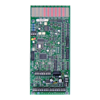
Explains the function of Group, Output, and System Status LEDs on the controller.
Explains various status, communication (RX/TX), and watchdog LEDs.
Covers input terminal blocks and expansion connectors for the controller.
Details input power jumper, analog input capabilities, and output terminals.
Describes pushbuttons, power supply protection, network terminals, and diagnostics.
Details input capacity, timer settings, and durations.
Explains relay refresh capability and procedures for naming inputs.
Describes six different input types: Maintained, Momentary, Linked On, etc.
Describes advanced input types like Linked On, Change State, and analog input.
Covers input polarity settings and the output flash warning feature.
Explains input priority hierarchy and how to view current input status.
Details output limits, group on-time after flash, and flash off-time.
Explains relay energize time and assigning outputs to groups.
Covers naming groups and creating super groups for logical control.
Explains serial command priority and how to check for faulty relays.
Details automatic output sequencing, manual override, and setting network address.
Covers setting network address, LED behavior, and controller reset procedures.
Explains pushbutton mode timeouts and network integration capabilities.
Provides step-by-step instructions for installing the LP-PK software.
Guides users through the process of registering the LP-PK software online.
Instructions for connecting LP-PK to various controller setups.
Steps for setting up databases connected or disconnected from the controller.
Explains the core function of assigning inputs to outputs via groups.
Demonstrates the LP Programming Kit interface for setup.
Details setting the number of inputs and timer durations.
Explains group assignment and supergroup functionality.
How to name inputs individually or automatically.
Describes the six available input types: Maintained, Momentary, Linked On, etc.
Covers setting input polarity and type.
Explains how to link inputs to output groups and timers.
How to configure flash warning for outputs.
Explains priority levels for maintained inputs.
How to monitor the status of inputs.
Setting the number of outputs to be controlled.
Details 'On-Time After Flash' and 'Flash Off-Time' parameters.
Configures output refresh rate and energize duration.
How to add outputs/circuits to specific groups.
Procedures for naming groups for identification.
How to create super groups for logical grouping of multiple groups.
Setting priority for serial commands over other input types.
How to check and change the state of groups and their outputs.
Feature to identify relays or circuits not in the correct state.
How to change controller address and view communication status.
Procedures for naming controllers and opening saved configuration files.
How to save configuration files and add descriptions.
Details special options like JC N2 Protocol and Timer alternations.
Steps to transfer configuration data from LP-PK to the LRP Controller.
How to retrieve configuration data from the LRP Controller.
How to print the LRP Controller database for records.
Common issues and solutions for outputs not functioning correctly.
Solutions for communication failures or blinking LEDs.
Troubleshooting steps when System Status LED 2 is not on.
Template for scheduling groups 01-30 with various parameters.
Template for scheduling groups 31-60 with various parameters.
Template for configuring switch inputs, types, and assignments.
| Brand | Lumisys |
|---|---|
| Model | LRP |
| Category | Controller |
| Language | English |