6-12
Engineering Guide CDA3000
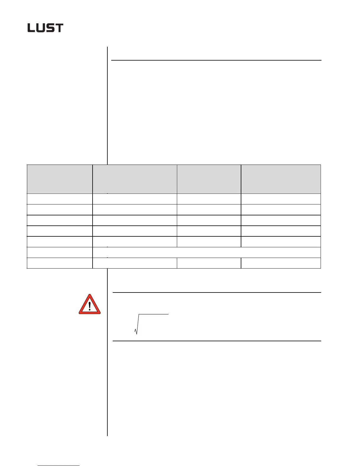
6 Selection of supplementary components
6.3 Braking
resistors
6.3.1 Technical data
of series BRxxx,
xx-xx
The sampling time T must be <150 sec.
Function Effect
• Use of braking resistors in the braking
chopper electronics integrated as
standard in the inverter module permits
two and four-quadrant operation (brak-
ing and driving).
• When the motor is braked electrical
energy is fed to the inverter module. To
prevent the DC-link voltage of the
inverter from reaching impermissible
values in such cases, the braking
energy in the braking resistor is con-
verted into heat.
Technical data
BR-270.02, XX0
BR-160.02,
XX0
BR-270.03, XX1
BR-160.03,
XX1
BR-090.03,
XX1
BR-090.10, XX1 to
BR-010.80,
XX1
Surface temperature > 200° C < 80° C < 80° C
Touch protection no yes (< 80° C) yes (< 80° C)
Voltage max. 800 V max. 800 V max. 800 V
High-voltage strength 4000 V 4000 V 1800 V
Temperature monitoring yes yes yes
Acceptance tests CE
Connection 1 m long PTFE-insulated litz wire Ceramic terminals Ceramic terminals
Table 6.10 Technical data of braking resistors
P
eff
P
S
2
t
ST
…⋅
T
--------------------------=

 Loading...
