7-2
Engineering Guide CDA3000
7 System installation
7.1 Heat discharge
from the switch
cabinet
7.1.1 Basic terms for
calculation
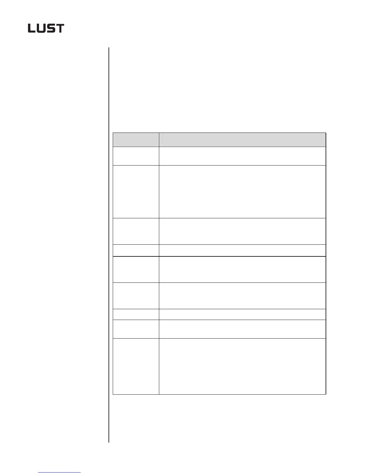
A number of calculations must be carried out in order to be able to dimen-
sion the air-conditioning components correctly. The following variables
are key to the calculations:
Basic terms Explanations
Q
V
[Watt]
Power loss (heat output) of the electrical components installed in the
switch cabinet.
Q
S
[Watt]
Heat output introduced or emitted via the effective switch cabinet sur-
face (to VDE 0660 Part 500).
If the interior temperature of the cabinet is higher than the ambient tem-
perature (T
i
> T
u
), heat is emitted from the cabinet (Q
S
>0). If the ambi-
ent temperature is higher than the interior temperature (T
i
<T
u
), heat is
radiated into the cabinet (Q
s
< 0).
Q
E
[Watt]
Necessary cooling power of an air-conditioning component; this refers
to the heat output which the device must discharge from the switch
cabinet.
Q
H
[Watt]
Necessary heat output of a switch cabinet heater.
T
i
[°C]
Maximum permissible cabinet interior temperature specified by the
manufacturers of the electrical components. As a rule it is between
+35°C and +45°C.
T
u
[°C]
Maximum ambient temperature at which fault-free functioning of all
electronic components in the switch cabinet or electronics housing
must still be guaranteed.
V [m³/h] Necessary volumetric flow of a filter fan.
A {m²]
Effective switch cabinet surface calculated according to DIN 57 660 Part
500 / VDE 0660 Part 500.
k [W/m²K]
Heat transfer coefficient of the switch cabinet. It is defined by the fol-
lowing equation:
k
l
l
α
i
-----
s
λ
---
l
α
a
------++
----------------------------=