2-6
Engineering Guide CDA3000
2 Drive definition
2.2 Drive definition
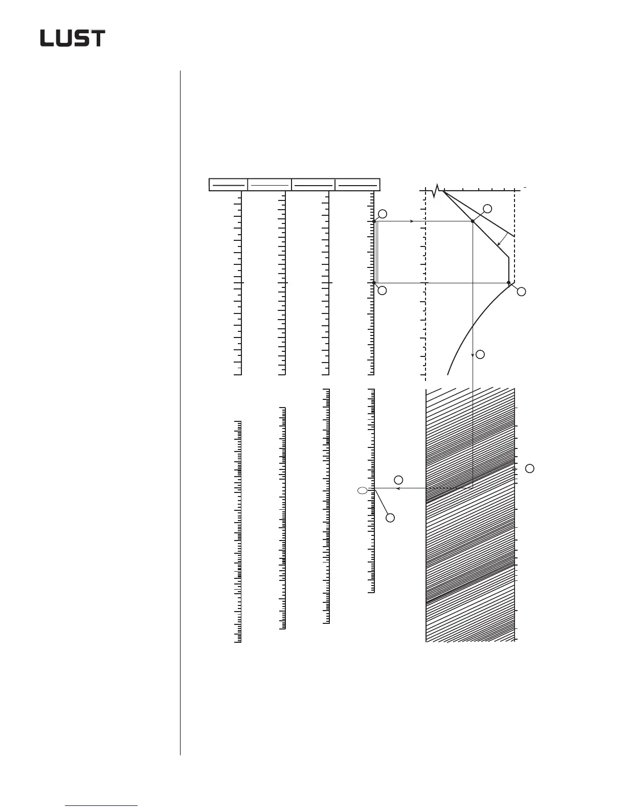
via normogram
he normogram provides user-friendly graphical power ratings for
applications with IEC standard motor. It is primarily used to define the
power outputs of rotational drives such as winders, mills, extruders, cen-
trifuges, mixers, etc. Any break-away torques or load surges occurring
must be calculated separately.
You will find the copy template in the appendix under "Practical working
aids for the project engineer". Continuous load characteristic - See sec-
tion 2.5.1.
Using the normogram:
1. Plot the speed vertices
for the relevant motor.
2. Draw two straight lines
to the continuous load
characteristic.
3. Connect the lowest
point on the continuous
load characteristic to
the load torque by a
straight line.
4. Connect the load tor-
que to the rated power
by a straight line.
5. Select your product
based on the perfor-
mance rating data.
Engine speeds
Continuous load characteristic in
inverter operation with IEC standard motor
2
2,5
3
4
5
6
7
8
9
10
15
20
25
30
40
50
60
70
80
90
100
P
N UR
[kW]
150
200
250
300
2
2,5
3
4
5
6
7
8
9
10
15
20
25
30
40
50
60
70
80
90
100
150
200
250
300
2
2,5
3
4
5
6
7
8
9
10
15
20
25
30
40
50
60
70
80
90
100
150
200
250
300
400
4
5
6
7
8
9
10
15
20
25
30
40
50
60
70
80
90
100
150
200
250
300
400
Rated power, inverter and motor
0,5
0,6 0,7 0,8
0,9 1,0
M
M
M UR
f [Hz]
10
20
30
40
50
60
70
80
90
100
750 rpm
8-pole
100
200
300
400
500
600
700
800
750
900
1000
1100
1200
1300
1400
1500
200
400
600
800
1000
1200
1400
1000 rpm
6-pole
1600
1800
2000
1500 rpm
4-pole
200
400
600
800
1000
1200
1400
1500
1600
1800
2000
2200
2400
2600
2800
3000
3000 rpm
2-pole
n [rpm]
500
1000
1500
2000
3000
2500
3500
4000
4500
5000
6000
5500
6
10
20
30
40
50
60
70
80
90
100
200
300
400
500
600
700
800
900
1000
2000
3000
4000
M
[Nm]
Load torque
1.
1.
2.
3.
4.
2.
5.
P >