MAINTENANCE PROCEDURES
There are 6 positions numbered 1 to 6.
The calibration screws have 6 different
settings identified by numbers scribed
on their head.
The actual setting is the screw head
number aligned with the mark on the
pulley.
mmo2011-002-101_a
PULLEY SETTING
1. Mark
2. N umber
Each position modifies maximum en-
gine RPM by about 200 RPM .
Lower position numbers decrease en-
gine RPM in steps of 200 RPM and
higher position numbers increase it in
steps of 200 RPM.
Example:
Calibration screws initially set at posi-
tion 4 and changed to position 6 will
increase maximum engine RPM by
400 RPM.
Procedure
Loosen the lock nut just enough to get
the calibration screw head out of the
pulley and rotate to the desired posi-
tion. Do not completely remove the
lock nut.
Set all 3 calibration screws to the same
position.
Tighten lock nuts to 10 N•m ± 2 N•m
(89 lbf•in ±18lbf•in).
NOTICE
Do not completely re-
move calibration screw otherwise
internal washers will fall off. Al-
ways adjust all 3 calibratio n screws
and make sure they are all set to the
same position.
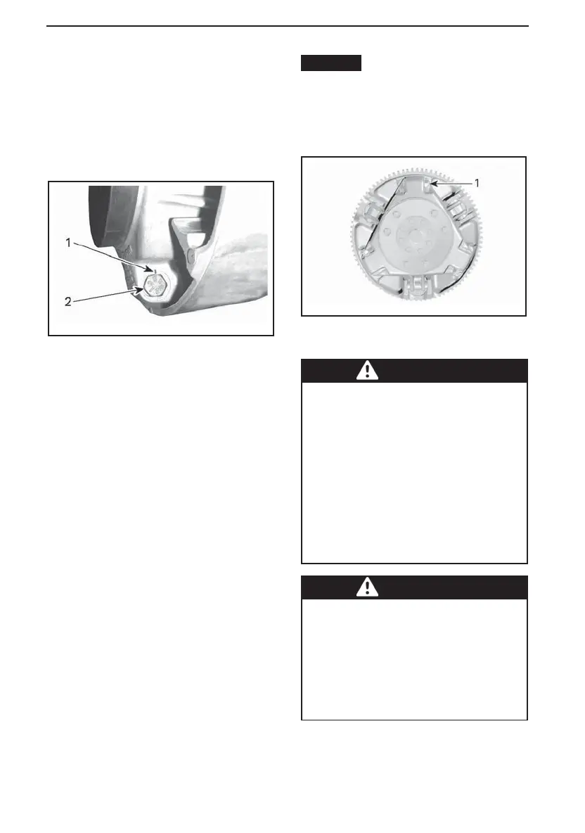
mmo2015-007-303_a
TYPICAL
1. L oosen just enough to permit rotating of
calibrate screw
WARNING
NEVER disassemble or modify the
drive pulley.
Improper assembly or modifica-
tions could cause the pulley to ex-
plode violently under the stress
generated by the high rotational
speed.
See your Lynx dealer to maintain
or service the drive pulley. Im-
proper servicing or maintenance
may affect performance and re-
duce belt life. Always respect
maintenance schedules.
WARNING
NEVER operate engine:
– Without shields and belt guard
securely installed.
– With hood and/or side panels
opened or removed.
NEVER attempt to make adjust-
ments to moving parts while en-
gine is running.
114
______________
 Loading...