214328 39 Revision A
Figure 4.11: GSL
CAUTION
Check to be sure all bystanders have cleared the area.
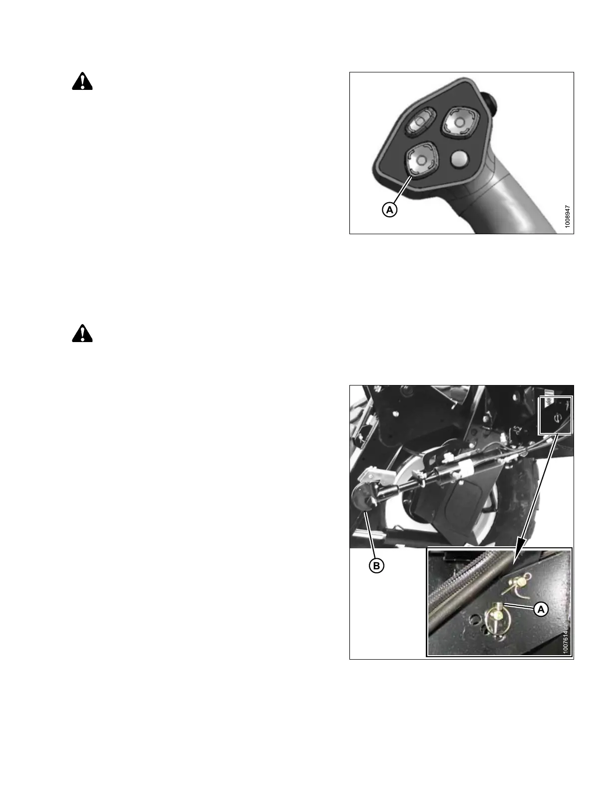
13. Start engine and activate HEADER DOWN switch (A)
on GSL to lower header fully.
14. Stop engine and remove key.
4.1.2 Hydraulic Link without Self-Alignment Kit
The following connection procedure applies to M155E4, M200, and M205 windrowers with non-self aligning
hydraulic center-links. This center-link configuration is optional for M105, M150, and M155 windrowers.
WARNING
To avoid bodily injury or death from unexpected startup of machine, always stop engine and remove key
before making adjustments to machine.
Figure 4.12: Center-Link
1. Stop engine and remove key.
2. Relocate pin (A) at frame linkage as required to position
hook (B) over header pin (not shown).
ATTACHING HEADER TO WINDROWER