MAINTENANCE/SERVICE
Form 169017 117 Issue – June 2008
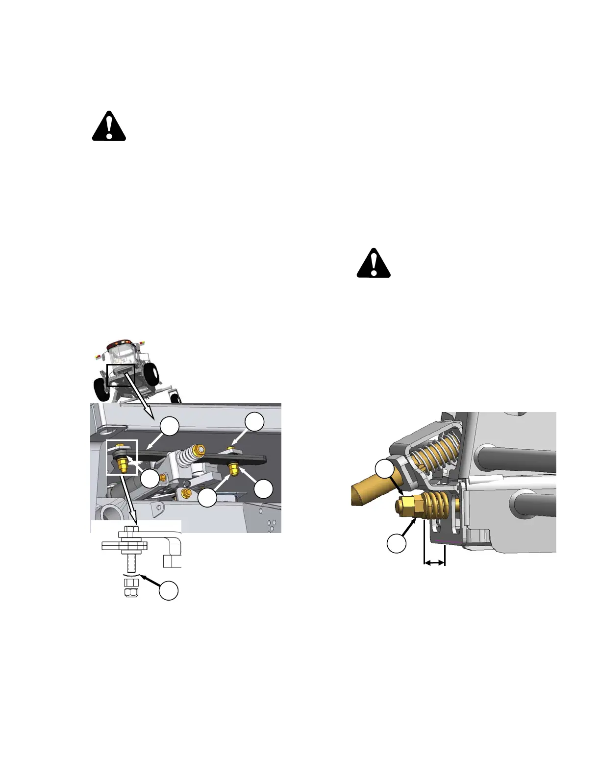
7.8.4 Steering Adjustments
7.8.4.1 Steering Link Pivots
DANGER
Stop engine and remove key from ignition
before leaving operator's seat for any
reason. A child or even a pet could engage
an idling machine.
a. Check for interference of moving parts with
hoses, tubes, other linkages in all positions of
steering wheel and GSL.
b. Check steering link attachments for looseness.
Inspect plastic bushings (A) at connection points
and check tightness of bolts (B). If bolts are
loose or bushings are worn or damaged, refer
illustration and proceed as follows:
c. Place GSL in N-DETENT, shutdown engine and
remove key.
d. If bolts (B) are loose:
1. Back off lower nut (C).
2. Tighten upper nut (D) until spring washer (F)
is flat, and then back off 1 to 2 flats (1/6 to
1/3 turn).
3. Hold upper nut (D) and tighten lower nut (C)
to 60-70 ft-lbf (81-95 N·m).
e. If bushings are worn, replace as follows:
1. Remove bolts (B) and remove link (E).
2. Remove plastic bushings (A) and replace
with new ones.
3. Attach link (E) to arms with bolts (B), spring
washer (F), and nuts (C) and (D). Ensure
spring washer (F) is orientated as shown.
4. Tighten upper nut (D) until spring washer (F)
is flat, and then back off 1 to 2 flats (1/6 to
1/3 turn).
5. Hold upper nut (D) and tighten lower nut (C)
to 60-70 ft-lbf (81-95 N·m)..
6. Perform checks for neutral interlock and
steering lock. Refer to Section 7.8.2. Safety
Systems.
7.8.4.2 Steering Chain Tension
DANGER
Stop engine and remove key from ignition
before leaving operator's seat for any
reason. A child or even a pet could engage
an idling machine.
a. Check steering for binding or excessive play
which may be the result of the steering chain
being too tight or too loose. If the chain tension
requires adjustment, proceed as follows:
b. Swivel the operator’s station to position steering
column close to the door.
c. At the base of the steering column, check
dimension “X” at spring (H). It should be 0.625
inches (16 mm).
d. Adjust dimension as follows:
1. Loosen nut (J) and turn nut (K) to achieve
0.625 inches (16 mm) dimension.
2. Tighten nut (J) against nut (K) to secure
position.
3. Check that steering chain is taut and
steering shaft is free to rotate.
0.625 in.
16 mm
K
J
C
B
D
E
A
F