OPERATOR’S STATION
Form # 169017 42 Issue – June 2008
DETAILED PROGRAMMING INSTRUCTIONS
(Key On / Engine Running or Not / Header Disengaged).
(Press PROGRAM and SELECT on CDM to enter programming mode).
NOTE: ENGINE MUST BE RUNNING TO CALIBRATE SENSORS (Page 44).
(continued next page)
L1 D130
TR
CTOR SETUP?
L2 C140
NO / YES C
BDISPL
YSETUP?
L1 D 1 3 0
SET KN I FE SPEED?
L2 C 1 4 0
1200 SPM
L1 D 1 3 0
KN I FE O
ERLO
DSPD?
L2 C 1 4 0
1000 SPM
or
L1 D 1 3 0
DISK O
ERLO
DSPD?
L2 C 1 4 0
2000 RPM
L1 D 1 3 0
O
ERLO
D PRESSURE?
L2 C 1 4 0
4000 PSI
L1 D 1 3 0
HE
DER I NDEX MODE?
L2 C 1 4 0
REEL & CON
EYOR
L2 C 1 4 0
REEL ONLY
L1 D 1 3 0
RE TURN TO CUT MODE?
L2 C 1 4 0
HEIGHT & TILT
L2 C 1 4 0
HEIGHT ONLY
L1 D 1 3 0
DW
INST
LLED?
L2 C 1 4 0
N O / Y E S H E
DER CUT WI DTH?
L1 D130
SW
P DW
CONTROL S?
L2 C140
NO/ YES
L1 D 1 3 0
HE
DER CUT WI DTH?
L2 C 1 4 0
20.5 FEET
L1 D 1 3 0
H
Y CONDITIONER?
L2 C 1 4 0
N O / Y E S
L1 D 1 3 0
UGER HDR REEL SPD
L2 C 1 4 0
RPM / MPH
L2 C 1 4 0
RPM / KPH
L1 D 1 3 0
SET T I RE S I ZE?
L2 C 1 4 0
18.4X26 TURF
L2 C 1 4 0
18.4X26 B
R
L2 C 1 4 0
23.1X26 TURF
L2 C 1 4 0
600 - 65 R28
L1 D 1 3 0
SET ENG I NE I SC RPM?
L2 C 1 4 0
NO / YES SET CONTROL LOCKS?
L1 D130
PRESS 4 - W
YS TO SET
L2 C140
ISC RPM OFF
L1 D130
PRESS 4 - W
YS TO SET
L2 C140
ISC RPM 2000
L1 D130
PRESS 4 - W
YS TO SET
L2 C140
ISC RPM 1900
L1 D130
PRESS 4 - W
YS TO SET
L2 C140
ISC RPM 1800
L1 D130
EX I T ENG I NE I SC?
L2 C140
NO / YES PRESS 4 - W
YS TO SET
If "NO" then jump to:
Pressing "SELECT" will go to the next line 1
(L1) menu selection. The turn signal "arrow"
keys are used to change the values.
If "NO" then jump to:
This is used to set the Intermediate Speed
Control function for the engine. The default or
last selected rpm will be displayed first and will
be flashing.
The "arrow" keys are used to cycle between the
selections. When "SELECT" is pressed the
program goes to the EXIT ENGINE ISC? menu
selection.
DRAPER HEADER ONLY. Default will be
flashing. Use "arrow" keys to select.
AUGER HEADER ONLY
For IMPERIAL display.
For METRIC display.
Use the "arrow" keys to set the header cut
width. The header ID appears at the RHS.
If "NO" then jump to:
Swaps the GSL reel fore / aft with the DWA console
controls. If NO jump to DWA AUTO UP & DOWN?
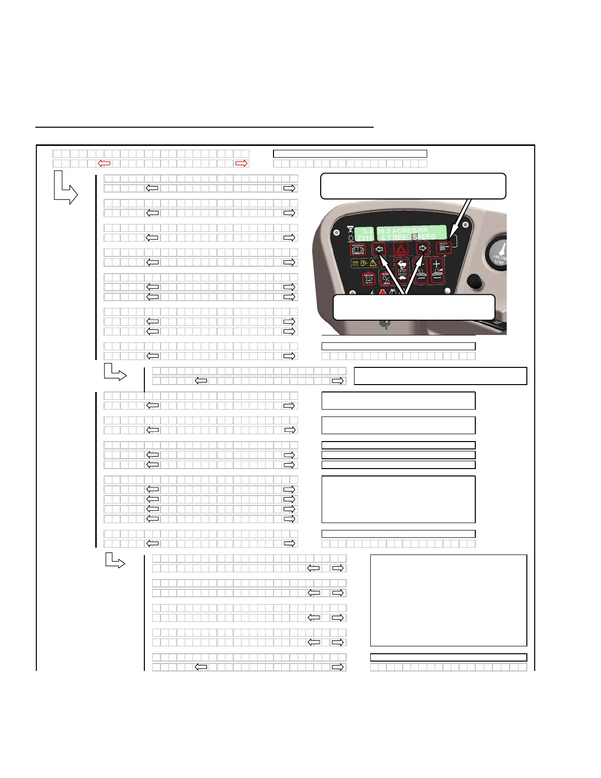
Programming Menu Flow Chart
If "NO" then jump to:
When the programming mode is entered the
header ID will be displayed on the top line of the
CDM using the last 4 display positions.
Pressing "SELECT" will go to the next line 1
(L1) menu selection. The turn signal "arrow"
keys are used to change the values. Pressing
"PROGRAM" at any time will cancel the
programming mode / menus and return back to
the main operating displays.
SELECT SWITCH
Press to Advance to Next Item On Upper Line.
TURN SIGNAL SWITCHES
Press to Change Values on Lower Line