64
57-606 ECLIPSE Model 706 Guided Wave Radar Transmitter
3
.4.5.3 Configuration using Custom Table
The following table provides an explanation of each of the
System Configuration parameters for open channel flow
applications using the Custom Table.
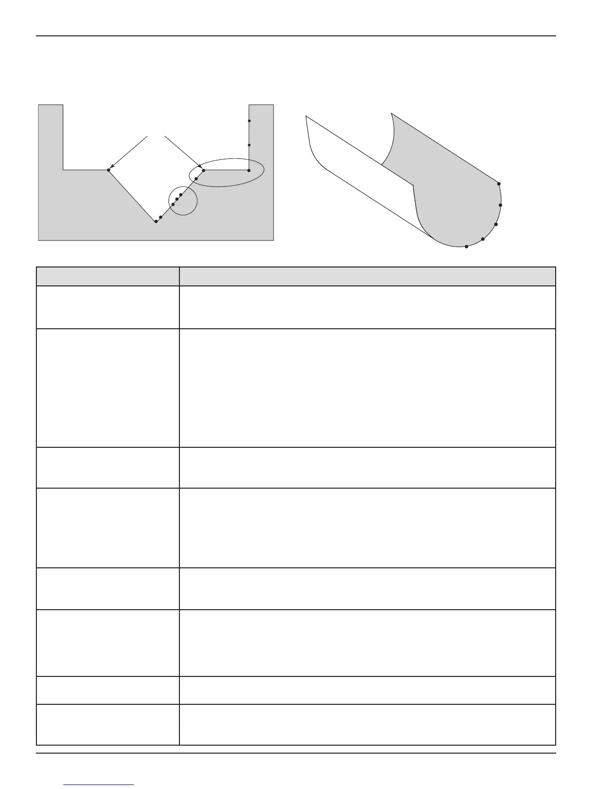
SPLINE OR LINEAR
SPLINE
P1
P2
P3
P4
P5
Concentrate points along curve
P2
P
3
P
7
P10
T
ransition
p
oint
P1
Concentrate points as follows:
A. At least two points at beginning (P1 and P2);
B. At least two points at end (P9 and P10);
C
. Three points at approximate average flow rate (for
example, P3, P4, P5); and at transition point (P7)
and points on either side (P6, P8).
P5
P
4
P
6
P
8
P
9
A
verage flow rate
Configuration Parameter
Explanation (Open Channel Flow — Custom Table)
Flow Units
A selection of Gallons/Minute (factory default ), Gallons/Hour,
Mil Gallons/Day, Liters/Second, Liters/Minute, Liters/Hour, Cubic Meters/Hour,
Cubic Ft/Second, Cubic Ft/Minute, and Cubic Ft/Hour are provided.
Flow Element
Select one of the following primary that are stored in the firmware:
Parshall flume sizes of 1", 2", 3", 6", 9", 12", 18", 24", 36", 48", 60", 72", 96",
120" and 144". Palmer-Bwls (Palmer-Bowlus) flume sizes of 4", 6", 8", 10", 12",
15", 18", 21", 24", 27" and 30". V-notch weir sizes of 22.5
O
, 30
O
, 45
O
, 60
O
, 90
O
and
120
O
. Rect with Ends (Rectangular Weir with End Contractions), Rect w/o Ends
(Rectangular Weir without End Contractions), and Cipoletti weir. Custom Table (see
page 65 can be selected if none of the stored can be used. The
table can be built with a maximum of 30 points. The Model 706 also has the capa-
bility of using a Generic Equation (see page 66) for flow calculation.
Custom Table
The points can be a Linear (straight line between adjacent points) or
Spline (can be a curved line between points) relationship. Refer to the drawing
above for more information.
Cust Table Vals
A maximum of 30 points can be used in building the . Each pair of val-
ues will have a Head (height) in the units chosen in the screen, and the
associated flow for that Head value. The values must be monotonic, i.e., each pair
of values must be greater than the previous Head/flow pair. The last pair of values
should have the highest Head value (usually the value) and the flow
associated with that Head value.
Reference Dist
The is measured from the sensor reference point to the point
of zero flow in the weir or flume. This must be measured very accurately in the
user-selected level units.
Maximum Head
is the highest liquid level (Head) value in the flume or weir before
the flow equation is no longer valid. The is expressed in the user-
selected . The Model 706 will default to the largest value
that is allowed for any given flume or weir. The value can be revised
depending on the value of the , or for end user preference.
Maximum Flow
is a read-only value that represents the flow value corresponding
to the value for the flume or weir.
Low Flow Cutoff
The (in user-selected level units) will force the calculated flow
value to zero whenever the is below this point. This parameter will have a
default and minimum value of zero.