MAN B&W 7.00
Page 3 of 6
MAN Diesel
MAN B&W ME-GI engines
198 88 81-9.2
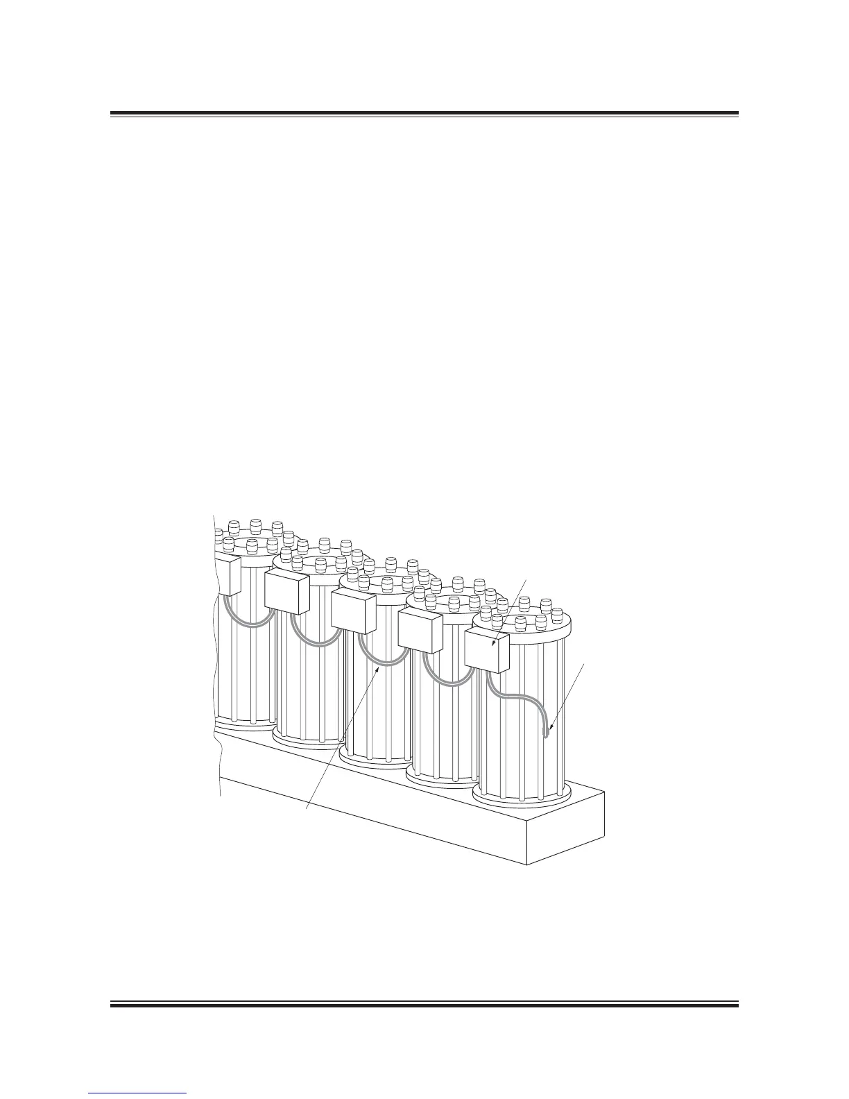
Gas piping on the engine
The layout of double-wall piping system for gas is
shown in Fig. 7.00.02. The high-pressure gas from
the compressor unit or the high-pressure pumps
(vaporiser) flows through the main pipe and dis-
tributed via flexible chain pipes to each cylinder`s
gas control block. The flexible chain pipes per-
form two important tasks:
• To separate each cylinder unit from each other
in terms of gas dynamics, utilising the well-
proven design philosophy of the ME engine`s
fuel oil system
• Act as flexible connections between the engine
structure and safeguarding against extra stress-
es in the gas supply and chain pipes caused by
the inevitable differences in thermal expansion
of the gas pipe system and the engine structure.
The large volume accumulator contains about 20
times the injection amount per stroke at MCR and
performs two tasks:
• Supply the gas amount for injection at only a
slight, but predetermined, pressure drop
• Form an important part of the safety system,
see Section 18.08.
The gas injection valve is controlled by the control
oil system. This, in principle, consists of the ME
hydraulic control oil system and an ELGI valve,
supplying high-pressure control oil to the gas in-
jection valve, thereby controlling the timing and
opening of the gas valve.
Fig. 7.00.02: Layout of doublewall piping system for fuel gas
178 65 60-3.0
Gas control block
Gas fuel inlet
Chain pipe
 Loading...