1
2
3
4
Setting valve clearance
98
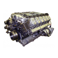
Fig. 1
Remove cylinder head cover.
Note:
On engines recently manufactured the
valve covers are fastened with Torx bolts
for which an E12 − ½” wrench is required.
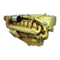
Fig. 2
Turn engine with engine cranking device until the
piston in the cylinder to be set is at TDC (Top Dead
Centre). At this point both inlet and exhaust valves
will be open i. e. valves overlap.
Note:
As far as possible turn engine only in di-
rection of rotation (anti-clockwise as seen
when looking at the flywheel) in order to
prevent the direction of rotation of the raw
water pump impeller being reversed.
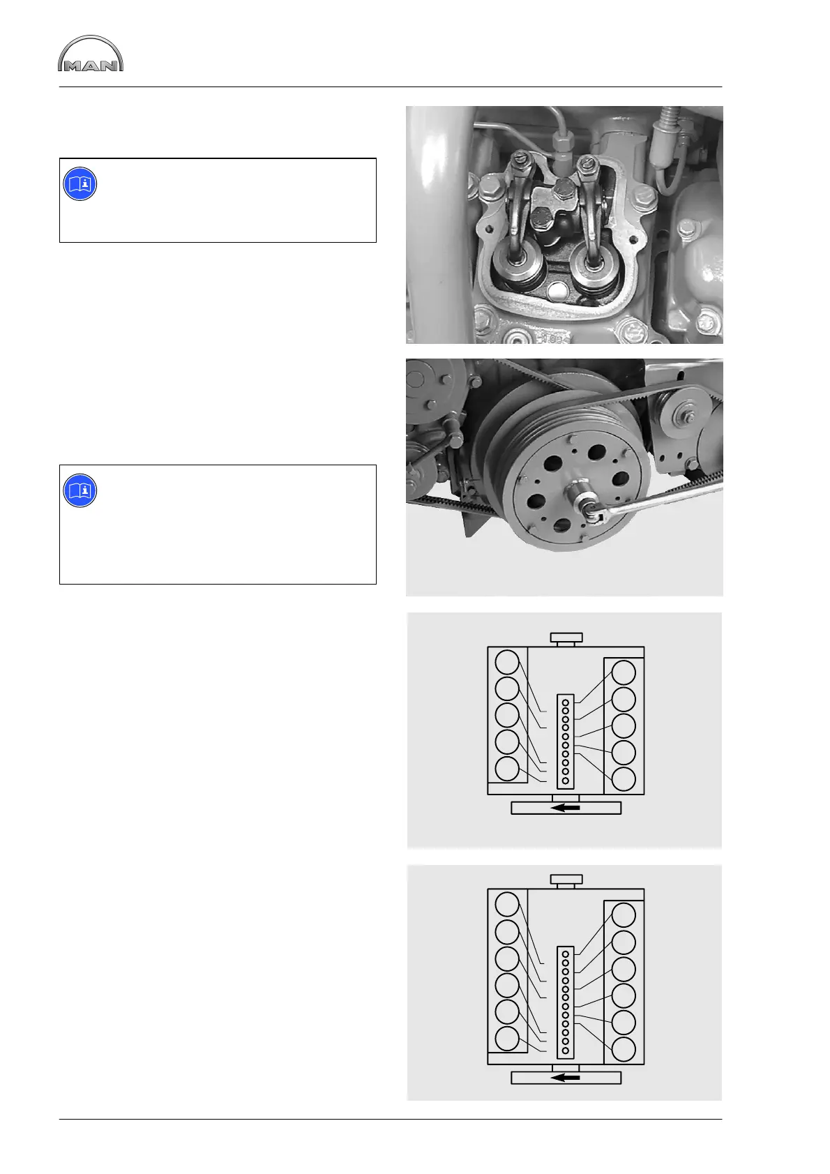
Fig. 3
D 2840 LE 301
Valves are in crossover in cylinder
165 10 2 7 3 8 4 9
7 3 8 4 9 1 6 5 10 2
Set valves in the cylinder
Fig. 4
D 2842 LE 301
Valves are in crossover in cylinder
1125 8 3 10 6 7 2 11 4 9
6 7 2 11 4 9 1 12 5 8 3 10
Set valves in the cylinder
1
4
8
7
6
5
4
3
2
1
6
7
8
9
10
2
3
5
9
10
2
5
8
7
6
5
4
3
2
1
8
9
10
3
4
6
9
10
7
1
11
12
11
12
 Loading...