1
2
3
Measuring axial / radial clearance of turbocharger shaft
89
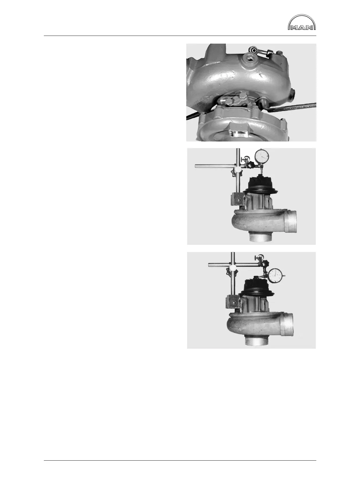
D Remove turbocharger, see page 87
Fig. 1
Mark the turbine housing relative to the bearing
housing and remove the turbine housing.
Axial clearance
Fig. 2
Arrange the dial gauge bracket with magnetic foot
and dial gauge as shown in the illustration. Apply
the dial gauge with initial tension on the face of the
shaft end of the turbine wheel.
Press the rotor shaft against the dial gauge, read
off and note the value. Press the rotor shaft in the
opposite direction, read off and note the value.
The difference between the values obtained is the
axial clearance.
Replace the turbocharger if this clearance is ex-
ceeded.
Radial clearance
Fig. 3
The radial clearance is measured only on the tur-
bine side with a dial gauge or feeler gauge.
Place the measuring tip of the dial gauge to the
side of the hub, press the turbine wheel to the dial
gauge, read off and note the value.
Press the turbine wheel in the opposite direction,
read off and note the value.
The difference between the values obtained is the
radial clearance.
Measure at several points.
If the play exceeds the permissible value, ex-
change turbocharger.
D Fit turbine housing,
−Ensure that the markings coincide−
D Tighten turbine housing bolts to specified
torque
D Installing turbocharger
 Loading...