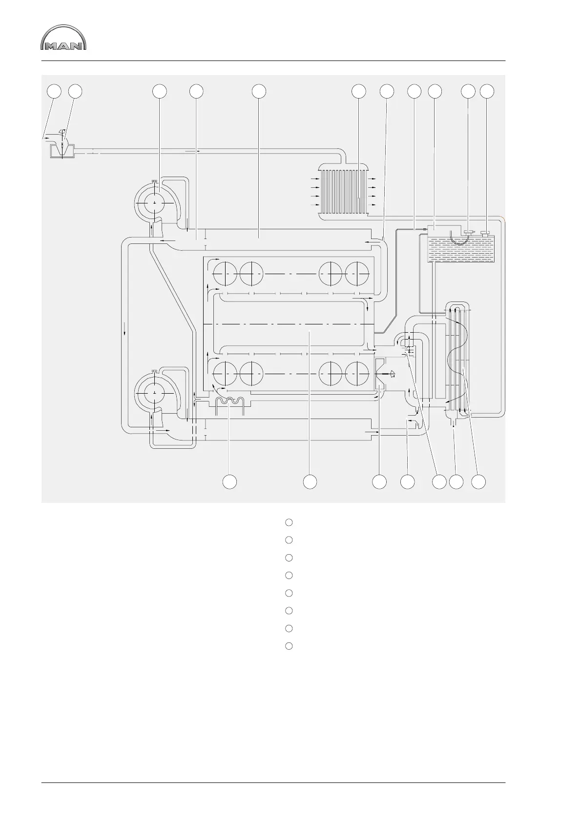
Schematic diagram of cooling system
22
1 2 3 4 5 6 7 8 9 10 11
12131415161718
À Sea water inlet
Á Sea water pump
 Exhaust turbocharger, liquid−cooled
à Exhaust manifold, liquid−cooled
Ä Exhaust pipe, liquid−cooled
Å Intercooler
Æ Coolant temperature measuring point
Ç Coolant line with throttle
È Expansion tank
É Positive pressure / negative pressure valve
11
Coolant filler neck
12
Heat exchanger, engine coolant / sea water
13
Sea water outlet
14
Thermostat
15
Heater feed and return system
16
Coolant pump
17
Crankcase
18
Engine oil cooler
 Loading...