5
6
7
Troubleshooting with GAC governor
146
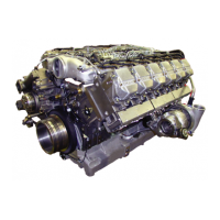
Fig. 5
Check final controlling element.
Remove both final controlling element cables from
control unit and measure resistance.
Correct value: 4,6 - 5 W
If value deviates, check cabling and plug. If cabling
and plug are in order, exchange final controlling
element.
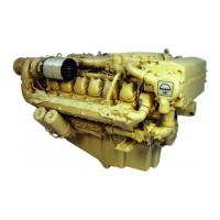
Fig. 6
If resistance as per Fig. 5 is in order, connect both
cables to battery voltage. The final controlling
element must then switch to max. position.
If it does not, the transmission linkage to the
injection pump control rod or the control rod itself
is blocked.
If linkage is in order, exchange final controlling
element.
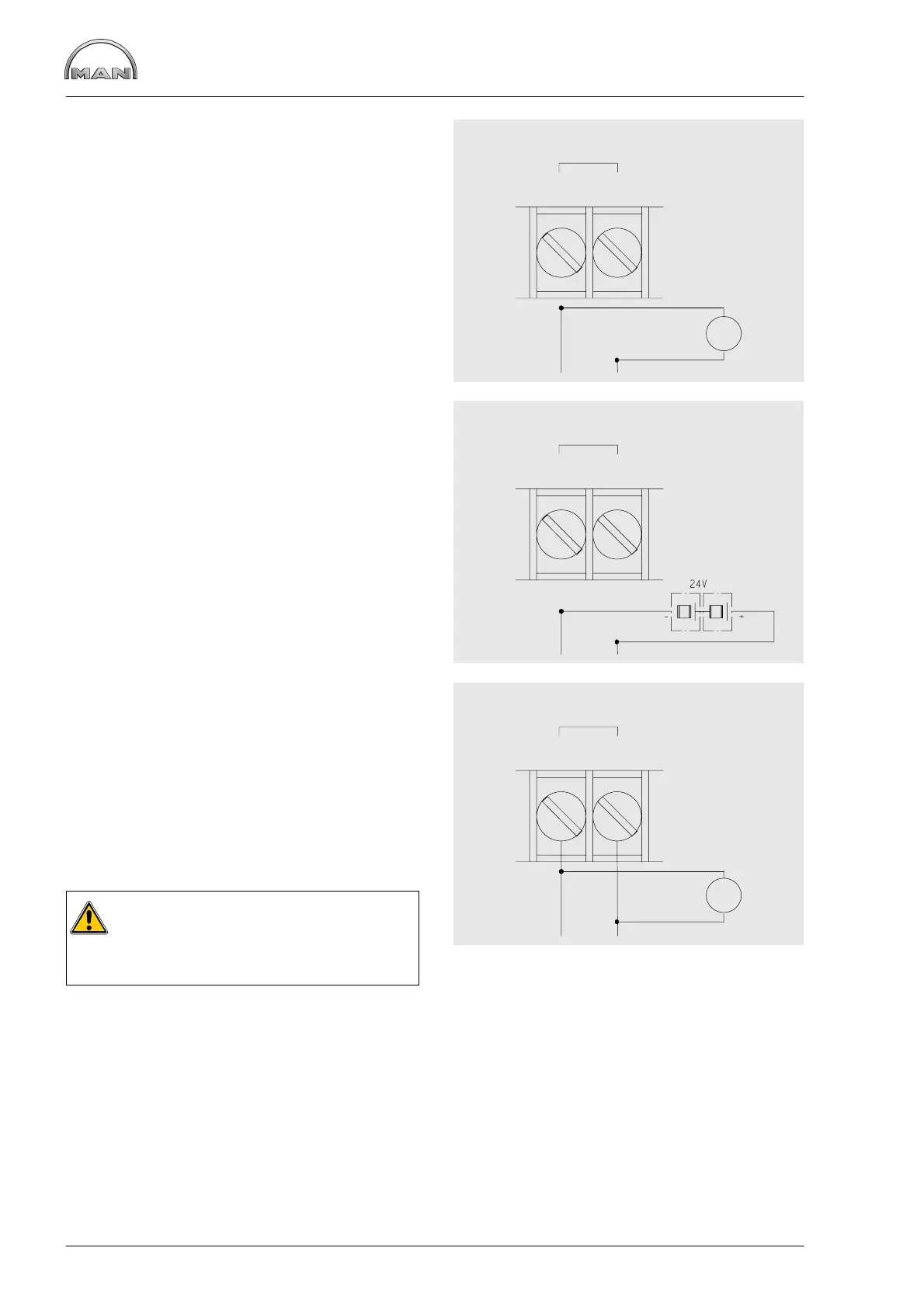
Fig. 7
If final controlling element is in order, but still fails
to move during the starting procedure, the output
voltage at the final controlling element terminals of
the control unit are to be checked during the
starting procedure.
Min. value: 17 V direct voltage
If no voltage is present, the control unit is
defective.
Caution:
Before installing a new control unit, always
check the cabling and the final controlling
element circuit for short circuits.
AB
ACTUATOR
W
AB
ACTUATOR
AB
ACTUATOR
V
_
 Loading...