ATTACHMENTS CD15 OPERATOR MANUAL
5-12 Published 3-30-2018, CTRL 636-05
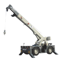
4 PART WIRE ROPE REEVING
Route the wire rope from the hoist over the boom head and
hook block sheaves as shown in Figure 5-10.
It may be easier to route the wire rope over the sheaves if
you remove the rope retention pins (1) from the boom head
and hook block. Install the pins after the wire rope is
installed.
Dead end the wire rope to the boom head with the socket
and wedge (1).
FIGURE 5-10
8928
1 Terminator Socket and Wedge
2 Pin with Retaining Pin
3 Rope Retention Pin (qty 4)
4 Boom Head Upper Sheave
5 Boom Head Lower Sheaves
6 Hook Block Sheaves (2 or 1)
5
2
1
3
4
1
4
5
6
1
4
5
6
4-Part Reeving
2-Part Reeving