Published 3-30-2018, CTRL 636-05 3-7
CD15 OPERATOR MANUAL OPERATING CONTROLS AND PROCEDURES
NOTE: ASME B30.5 specifies that if a crane is not level
within 1% of grade, the allowable capacities must
be reduced. Therefore, whether lifting on rubber or
outriggers, it is essential that the crane is level to
within 1% of grade. The bubble level that is
provided on the crane is calibrated to be accurate
within 1% of grade.
To properly level the crane, the boom must be
positioned over the front of the crane, fully lowered
to horizontal and fully retracted (for cranes fitted
with a boom rest, the boom shall be stowed onto
the rest). Raise and level the crane using the
outriggers; refer to Operating Outrigger Controls on
page 3-16.
A working crane may settle during lifting
operations. Frequently check the crane for level.
When rechecking the crane for level, the boom
must be positioned over the front of the crane, fully
lowered to horizontal and fully retracted (for cranes
fitted with a boom rest, the boom shall be stowed
onto the rest). If necessary, re-level the crane using
the procedures under Operating Outrigger Controls
on page 3-16.
NOTE: The bubble level adjustment should be checked
periodically; if it is suspected that the bubble level
is out of adjustment, verify and adjust the bubble
level as follows:
• Position the crane on a firm, level surface.
• Extend and set the outriggers. Level the crane,
as indicated by the bubble level indicator,
using the outriggers.
• Place a digital level, carpenter level, or similar
type device on a machined surface such as the
turntable bearing or bearing mounting
surfaces.
• Using the outriggers, level the crane as
indicated on the leveling device used in the
preceding step.
• Using the bubble level mounting screws,
adjust the bubble level to show level.
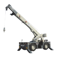
Boom Angle Indicator
See Figure 3-9 for the following procedure.
The boom angle indicator is a plumb arrow and a decal with
angular graduations. It is located on both sides of the boom
and is visible from the operator’s cab in most boom positions.
Use the indicator to determine the boom angle when reading
the capacity chart. See Section 4 of this manual.
The boom angle range on this crane is 0-70°.
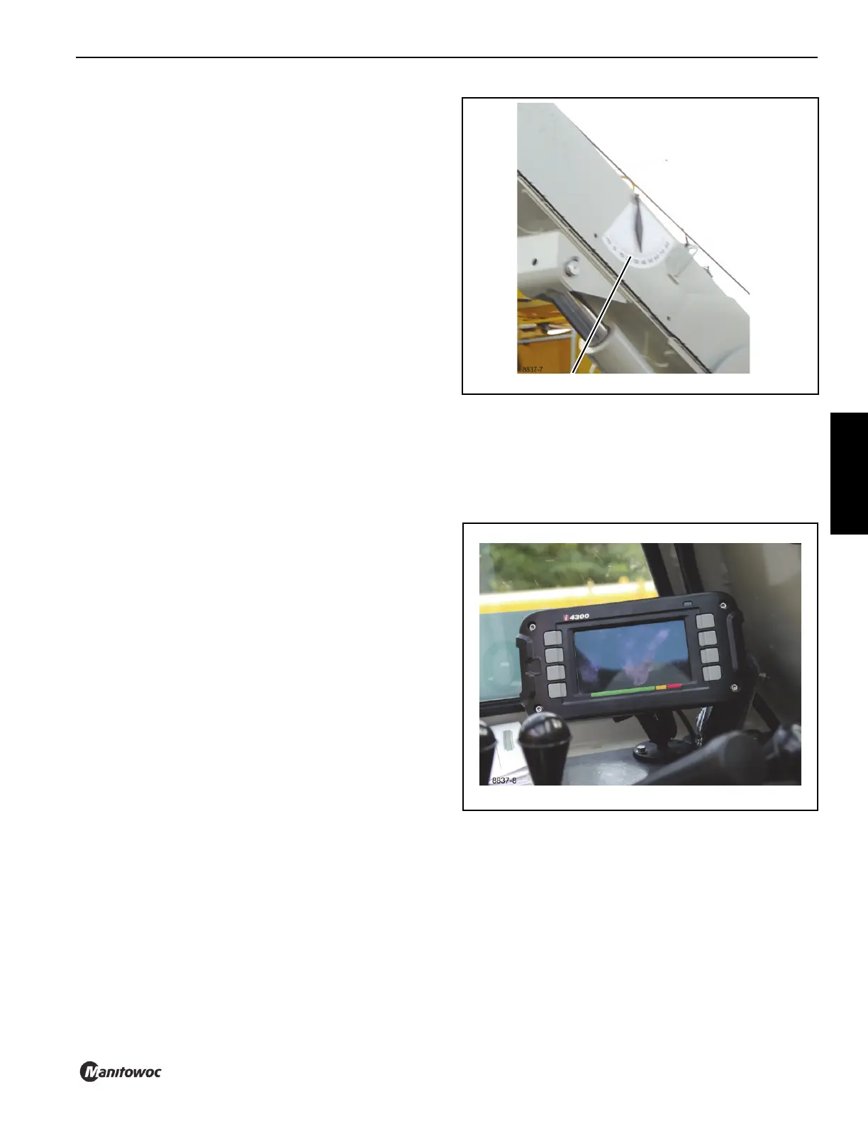
Rated Capacity Limiter (RCL)
The RCL (Figure 3-10) provides information on angle, load,
radius, capacity, etc. and allows the operator to set limits for
these variables.
For operating instructions, refer to the RCL manual provided.
8837-7
Boom Angle Indicator
FIGURE 3-9