OPERATING CONTROLS AND PROCEDURES CD15 OPERATOR MANUAL
3-6 Published 3-30-2018, CTRL 636-05
Ignition Switch
See Figure 3-7 for the following procedure.
The key included with this crane is necessary for operation of
the ignition switch.
ACC – maintained position energizes the accessory
electrical circuit.
STOP – maintained position stops the engine and de-
energizes the accessory electrical circuits.
ACC/RUN – maintained position energizes the
accessory and ignition electrical circuits.
START – momentary position which starts the engine.
Release the switch to the ACC/RUN position once the
engine starts.
See Starting the Engine on page 3-10.
NOTE: The engine stop and warning lights come on (self
test) briefly when the ignition switch is turned to the
ACC/IGN position. The park brake, transmission oil
temperature, and outrigger lights do not come on
(self test) when the ignition switch is turned to the
ACC/IGN position.
Operator Aids
Strobe Light
The amber strobe light behind the cab comes on when the
engine started
Dome Light
Use the switch on the dome light to turn it ON-OFF.
12 volt Accessory Outlet
See Figure 3-7 for the following procedure.
Use this outlet to power a 12 volt accessory with a maximum
amperage of 10 amps.
Crane Level Indicator
See Figure 3-8 for the following procedure.
A bubble-type level indicates crane levelness.
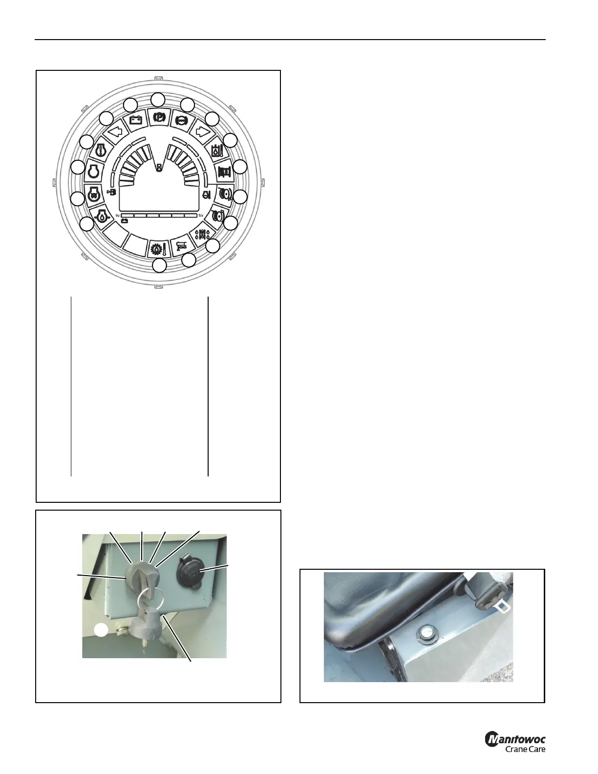
1
2
3
5
4
6
7
8
9
10
8964
1 Engine Oil Pressure Red
2 Wait To Start Amber
3 Engine Stop Red
4 Engine Warning Amber
5 Left Turn Signal Green
6Battery Red
7 Park Brake Activation Red
8 Low Brake Pressure Red
9 Right Turn Signal Green
10 Hydraulic Oil Temp Red
11 Minimum Wrap (on hoist drum) Red
12 Hoist UP Green
13 Hoist DOWN Green
14 4WD On Amber
15 Outrigger Monitoring Green
16 Transmission Oil Temperature Red
11
12
13
14
15
16
FIGURE 3-6
8837-5
Ignition
Switch
FIGURE 3-7
12V
Accessory
Outlet
Minimum Wrap/
Transmission Alarm
ACC
STOP
ACC/
RUN
START