Published 3-30-2018, CTRL 636-05 5-1
CD15 OPERATOR MANUAL ATTACHMENTS
SECTION 5
ATTACHMENTS
SECTION CONTENTS
Hook Block . . . . . . . . . . . . . . . . . . . . . . . . . . . . . . . 5-1
Removing the Hook Block. . . . . . . . . . . . . . . . . . . 5-1
Installing the Hook Block . . . . . . . . . . . . . . . . . . . 5-2
Downhaul Weight . . . . . . . . . . . . . . . . . . . . . . . . . . 5-2
Installing the Downhaul Weight. . . . . . . . . . . . . . . 5-2
Removing the Downhaul Weight. . . . . . . . . . . . . . 5-2
Boom Extension (Jib). . . . . . . . . . . . . . . . . . . . . . . 5-5
Installing the Boom Extension . . . . . . . . . . . . . . . 5-5
Stowing the Boom Extension . . . . . . . . . . . . . . . . 5-5
Pivoting Boom Head. . . . . . . . . . . . . . . . . . . . . . . . 5-7
Boom Head Positions . . . . . . . . . . . . . . . . . . . . . . 5-7
Changing the Boom Head Position
(without Boom Extension) . . . . . . . . . . . . . . . . . . . 5-7
Changing the Boom Extension Offset . . . . . . . . . . 5-7
Searcher Hook Assembly . . . . . . . . . . . . . . . . . . . . 5-9
Installation . . . . . . . . . . . . . . . . . . . . . . . . . . . . . . . 5-9
Removal. . . . . . . . . . . . . . . . . . . . . . . . . . . . . . . . . 5-9
Installing Cable On The Hoist. . . . . . . . . . . . . . . . 5-10
Wire Rope Wedge Socket . . . . . . . . . . . . . . . . . . . 5-10
4 Part Wire Rope Reeving. . . . . . . . . . . . . . . . . . . 5-12
HOOK BLOCK
Removing the Hook Block
1. Lower the hook block to the ground to place slack in the
wire rope.
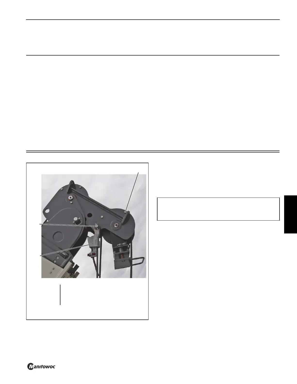
2. Remove the pin (2, Figure 5-1) securing the socket and
wedge socket (3) to the boom head.
3. If necessary, remove the socket and wedge from the
wire rope.
NOTE: When removing the hook block to install the
downhaul weight, the socket and wedge does not
have to be removed from the wire rope.
4. Remove the three rope retention pins (2, Figure 5-2).
5. Pull the wire rope and the socket and wedge though the
hook block.
6. Reinstall the three rope retention pins (2, Figure 5-2) in
the hook block.
8920
FIGURE 5-1
3
2
1
1 Rope Retention Pin (qty 4)
2 Pin with Retaining Pin
3 Terminator Socket and Wedge
CAUTION
Ensure that the hook block’s safety latch (Figure 5-2)
does not get damaged.