OPERATING CONTROLS AND PROCEDURES CD15 OPERATOR MANUAL
3-4 Published 3-30-2018, CTRL 636-05
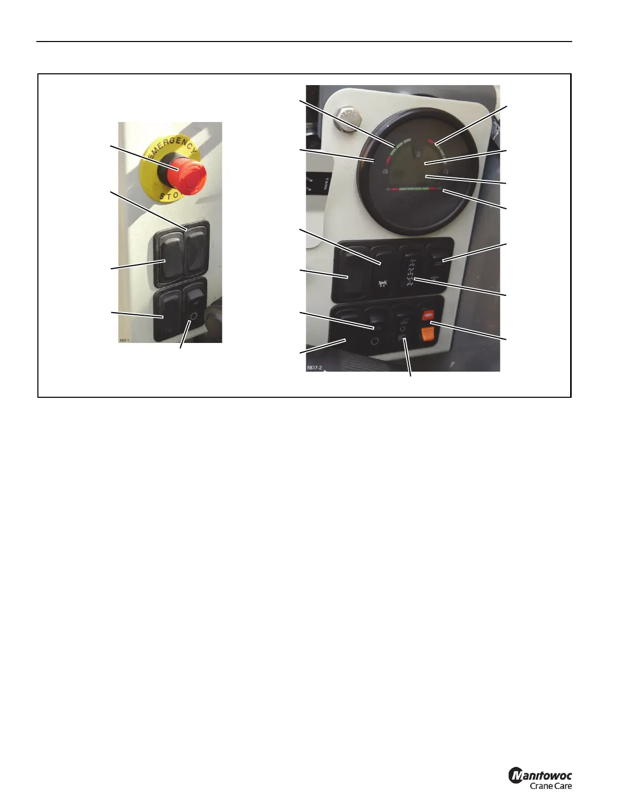
Panel Switches, Gauges, and Indicators
Item numbers in following headings correspond to item
numbers in Figure 3-5.
1 – Defroster Switch
This switch is used to start the defroster fans.
Top position – Fan ON.
Bottom position – Fan OFF.
2 – Heater Switch
This switch is used to operate the heater when equipped with
the heat only option.
Top position – operate heater in HIGH.
Center position – heater OFF.
Bottom position – operate heater in LOW.
3 – Auxiliary Winch Switch
This switch operates the optional winch attached under the
front end of the crane.
Top position (held down) – UNWIND rope from the winch
drum.
Center position – STOP the winch drum.
Bottom position (held down) – WIND rope onto the
winch drum.
4 – Fuel Switch
This switch is used to select the fuel type when equipped
with the duel-fuel engine option.
Top position – GAS.
Center position – OFF.
Bottom position – PROPANE.
5 – Emergency Stop Switch
Push knob DOWN to STOP engine only in an
emergency — for example, if a crane function does not
stop when the control handle is released to off or any
other uncontrolled motion of a crane function is
observed.
Beware — when the knob is pushed down, the engine
stops, the brakes apply, and any functions being
operated come to an abrupt stop.
NOTE: The knob must be pulled up before the engine can
be restarted.
Use the engine ignition switch to stop the engine
for normal operating conditions.
FIGURE 3-5
8837-2
8837-3
1
2
3
4
5
6
7
8
9
11
13
14
15
16
17
18
19
10
12