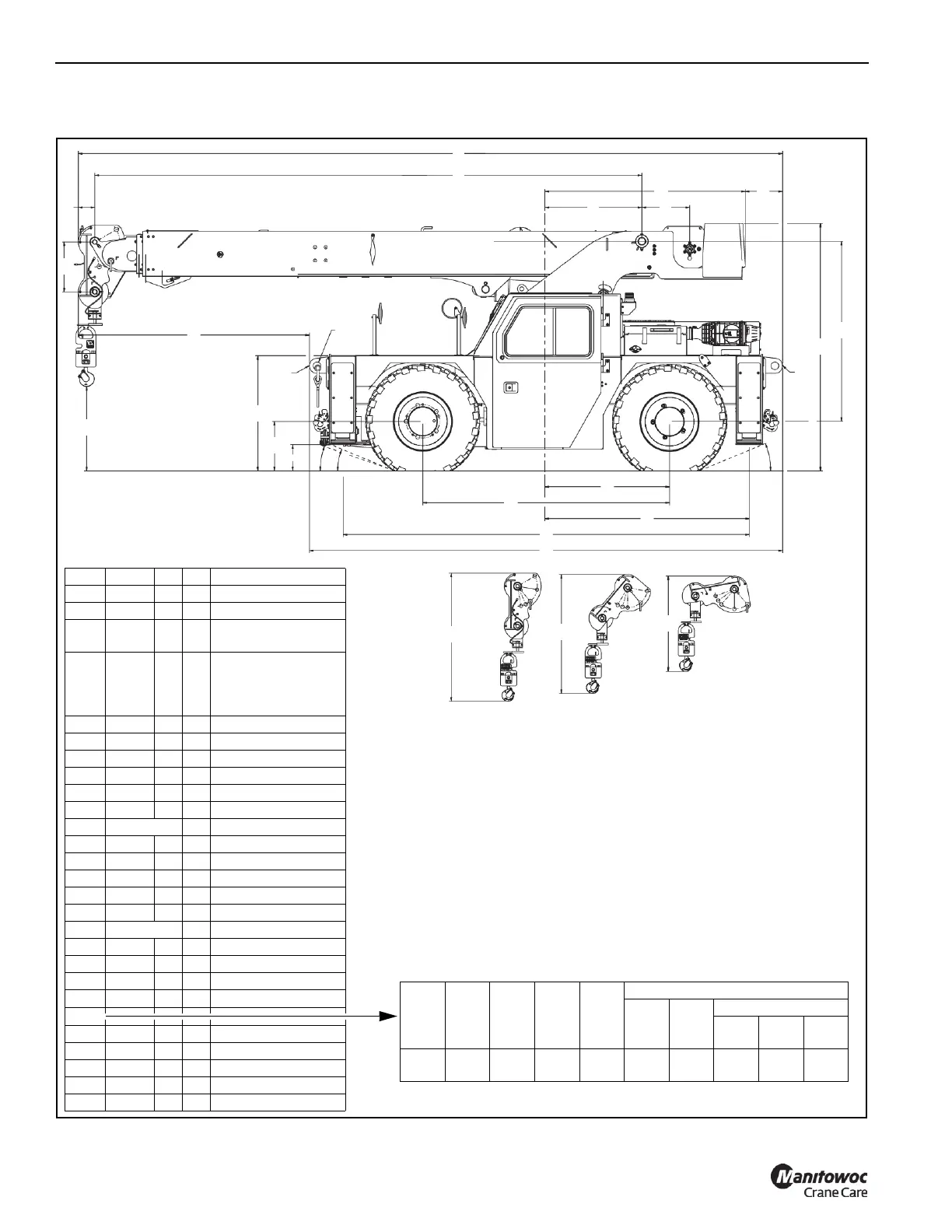
Item mm ft in Comments
A 500 1 8
B 165 0 7
C 7066
6853
23
22
2
6
41 ft Boom Retracted
50 ft Boom Retracted
D 5489
12500
5277
15253
18
41
17
50
0
0
4
1
41 ft Boom Retracted
41 ft Boom Extended
50 ft Boom Retracted
50 ft Boom Extended
E 2009 6 7
F 972 3 3
G 480 1 7
H 376 1 3
J 1805 5 11
K 2481 8 2
L22°
M 1250 4 1
N 2476 8 2
P 2050 6 9
Q 4075 13 5
R 4747 15 7
S 19° Optional
T 262 0 11
U 494 1 8
V 1154 3 10
W 2319
7
7
X
Y 76 0 3 4 lifting holes
Z 846 2 10
AA 1613 5 4 0° Boom Head
AB 1495 4 11 40° Boom Head
AC 1200 3 11 80° Boom Head
A
B
C
D
F
E
G
H
K
J
M
N
P
Q
R
T
U
V
X
X
Y
AA
AB
AC
Z
LS L
W
Item Qty Lift Tow
Tie
Down
Capacity – Metric Ton (US Ton)
Lift
Tow
Tie Down
Fore
Aft
Side Down
X 4 OK OK OK 25.4
(28)
25.4
(28)
25.4
(28)
7.3
(8)
25.4
(28)
NOTE 1: Lifting of the crane must be accomplished utilizing the specified fittings
indicated at “X”.
NOTE 2: Rigging personnel shall be responsible for proper selection and placement
of all slings and load handling devices.
NOTE 3: Dimensions and heights shown are for largest configuration available.
NOTE 4: Rigging personnel shall verify dimensions required for clearance.
NOTE 5: Do not use pintle hooks or counterweight lugs for lifting or tie down of the
crane.