Swing-away lattice
3.4 Description of the rigging work
3 - 38 3 112 441 en Lattice extension operating instructions
GMK 4100/4100-L/5095
11.01.2008
Establishing the connection
To establish the connection, the lattice extension must be on the run-up rail.
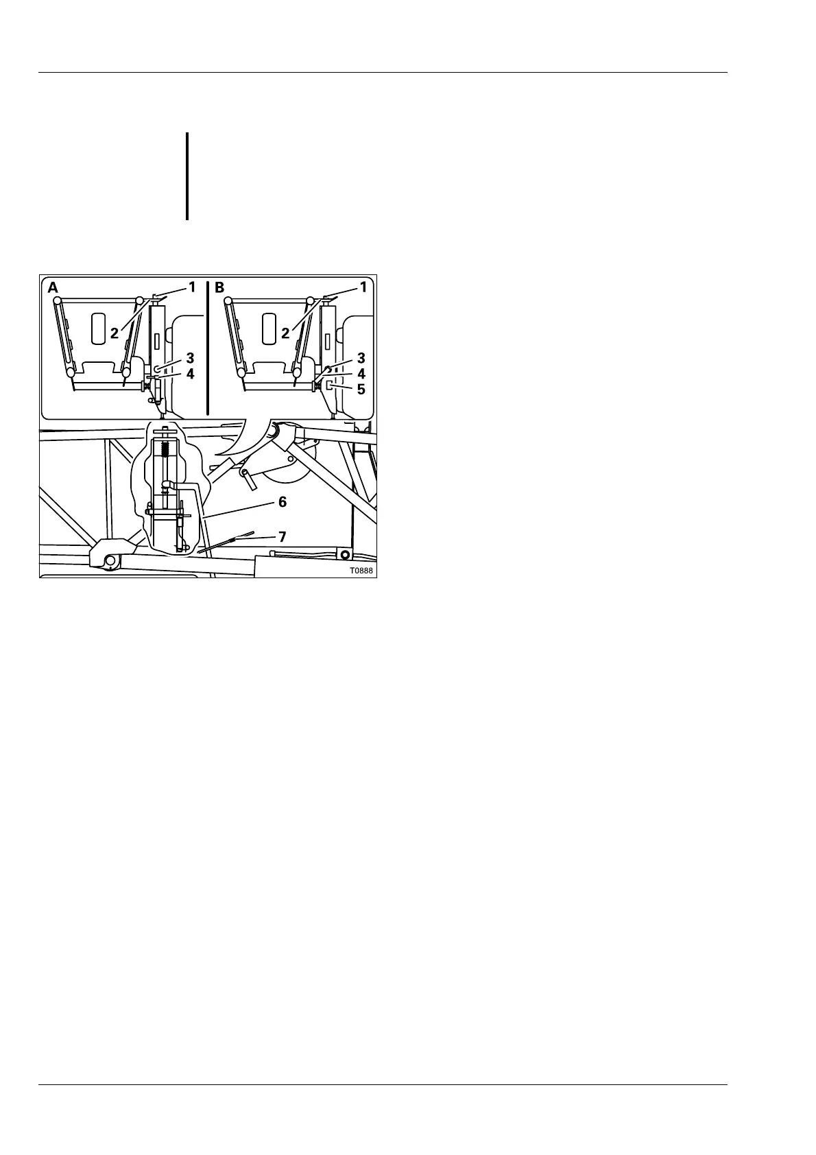
• (A) – Check whether the pin (4) has been
pulled out of the bore (3).
• Check whether the lever (6) is under the rest
(7).
• Swing the lattice extension on the run-up
rail sideways onto the main boom.
The slewing axle (1) is first pressed down by
the holder (2) and then engages in the holder.
• (B) – Check whether the slewing axle (1) pro-
trudes out of the top of the holder (2).
• Undo the retaining pin and take the pin (4)
out of the holder (5).
• Insert the pin (4) through the bores (3).
• Secure the pin (4) with the retaining pin.
The connection is now established. The pin (4)
prevents the retraction of the slewing axis and
fastens section 1 to the main boom.
G
Risk of accidents due to falling lattice extension
Attach section 1 to the main boom always with the pin (4). If section 1 is
only attached at the slewing axis, the lattice extension could slip out of the
slewing axle and fall down (e.g. when working with the main boom).
 Loading...