4-33
Published 3/26/2018, Control # 596-05
GRT8100 SERVICE MANUAL BOOM
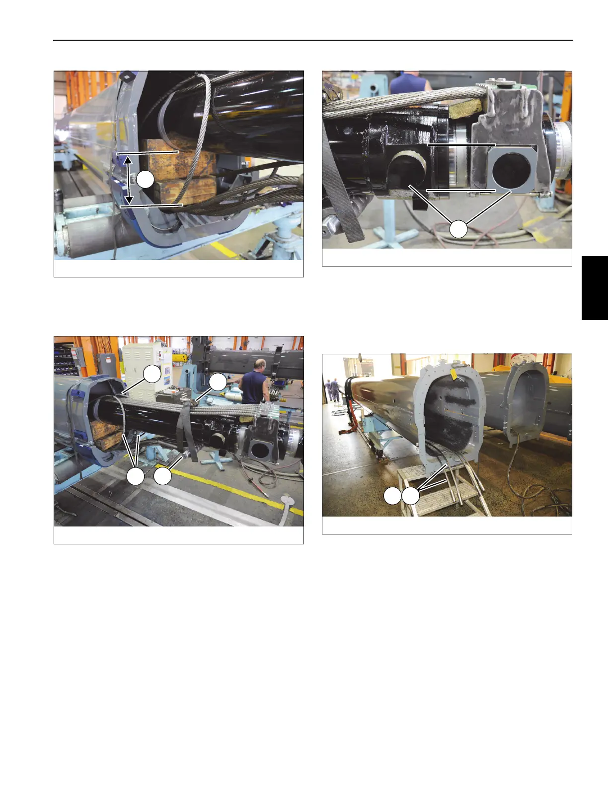
25. To ease installation of tele 4 (5) into tele 3 (4), insert
shaft (117) through anchor ends of the six tele 3 extend
cables (139), then secure cables to bottom of telescope
cylinder (6) using a strap (G) (see Figure 4-55).
26. Zip-tie (H) two tele 4 retract cables (114) together above
telescope cylinder (6) (see Figure 4-55).
27. Ensure lugs (J) on rear of telescope cylinder (6) are
indexed with one another (in-line with one another) (see
Figure 4-56).
28. Position tele 3 (4) up side down and in back of tele 4 (5).
Set tele 3 (4) on adequate supports.
29. Install tele 4 extend cables (2x-104, 2x-105) through
inside of tele 3 (4), ensuring the threaded ends of the
cables are at rear of tele 3 (4) and the anchor ends are at
the front (see Figure 4-57).
30. Insert threaded ends of tele 4 extend cables (2x-104, 2x-
105) through holes at rear of tele 3 (4). Use two custom-
made brackets (K) consisting of large washers
connected by a plate to separate the two sets of cables
from becoming tangled. Ensure the two tele 4 extend
cables (104) are positioned above the two tele 4 extend
cables (105) (see Figure 4-58).
FIGURE 4-55
8804-15
G
117
H
114

 Loading...


