BOOM GRT8100 SERVICE MANUAL
4-34
Published 3/26/2018, Control # 596-05
31. Using a grease gun or brush, apply grease to inside of
tele 3 (4) in the areas where the tele 4 rear wear pads
will touch upon assembly.
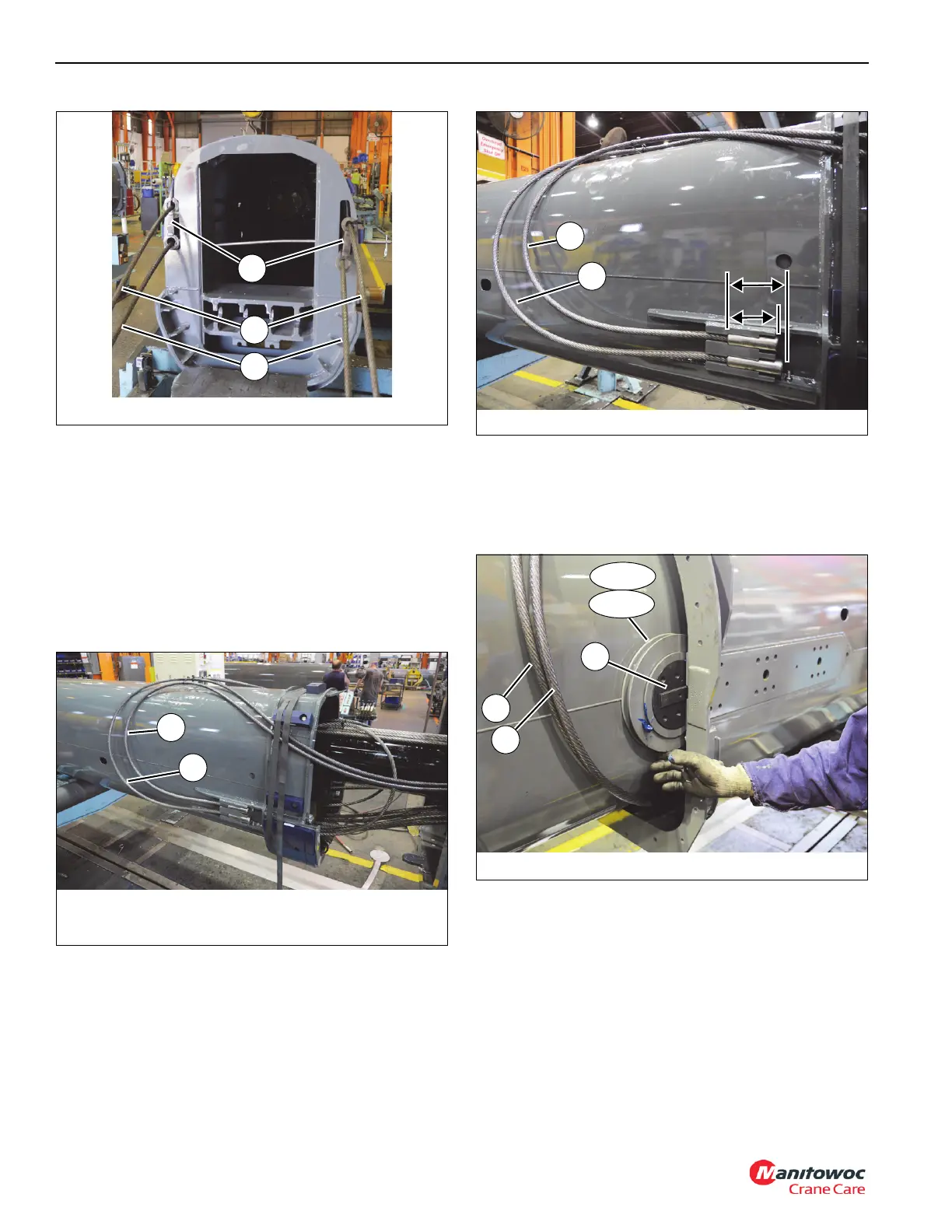
32. Attach anchor ends of tele 4 extend cables (2x-104, 2x-
105) to rear of tele 4 (5), ensuring cables with the shorter
anchors (105) are installed above cables with the longer
anchors (104). Loop extend cables (2x-104, 2x-105) up
to the top of the tele 3 (4) and zip-tie the two pairs of
cables together. Lock the four anchor ends of the cables
in place using four bolts (31) (see Figure 4-59 and
Figure 4-60).
33. Assemble small and large sheaves (2x-103, 2x-102),
four spacers (172), and four shafts (101) together.
34. Slide front tip of tele 4 (5) into tele 3 (4) until loops in the
four tele 4 extend cables (104, 105) are close to the tip of
tele 3 (4) (see Figure 4-61).
35. Install rear sheave assembly (103) into inside front of
tele 3 (4), ensuring the rectangular tab on shaft (101)
slides into the groove in tele 3 (4) (left and right sides)
(see Figure 4-61).
36. At rear of tele 3 (4), pull the two tele 4 extend cables
(105) until they seat into the left and right sheave
assemblies (103). Continue to pull cables until the bolts
holes of shafts (101) align with the holes in tele 3 (4).
Secure two shafts (101) to tele 3 (4) using twelve bolts
(108).
37. Install rear guard weldment (107) over tele 4 extend
cable (105), where the cable wraps around the sheave
FIGURE 4-58
8804-24
K
105
104
FIGURE 4-61
8804-19
102
Front
103
Rear
105
104
101

 Loading...


