4-35
Published 3/26/2018, Control # 596-05
GRT8100 SERVICE MANUAL BOOM
(103), and secure with the capscrew (141) (left and right
sides) (see Figure 4-62).
38. Install front sheave assembly (102) into inside front of
tele 3 (4), ensuring the rectangular tab on shaft (101)
slides into the grooves in tele 3 (4) (left and right sides)
(see Figure 4-61).
39. At rear of tele 3 (4), pull the two tele 4 extend cables
(104) until they seat into the left and right sheave
assemblies (102). Continue to pull cables until the bolt
holes of the shafts (101) align with holes in tele 3 (4).
Secure the two shafts (101) to tele 3 (4) using twelve
bolts (108).
40. Install rear guard weldment (106) over tele 4 extend
cable (104), where the cable wraps around the sheave
(102), and secure with capscrew (141) (left and right
sides).
41. Install grease fittings (109) into the four shafts (101). Add
grease until grease extrudes through the sheaves.
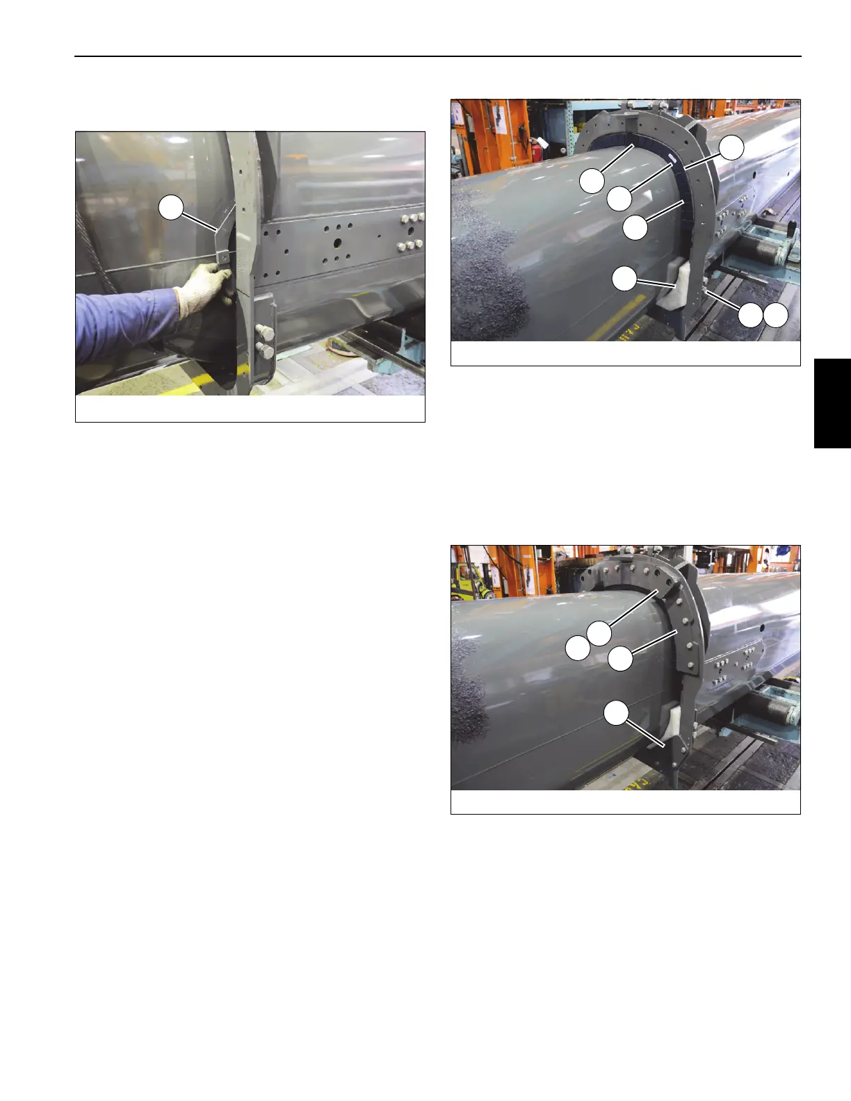
42. Further insert tele 4 (5) into tele 3 (4) until wear pads and
shims strapped to tele 4 (5) are near the front of tele 3
(4). Lift and lower tele 4 (5) as necessary until wear pads
and shims slip into tele 3 (4), then remove strap.
Continue to insert tele 4 (5) into tele 3 (4) until wear pads
and shims are fully inserted. (see Figure 4-63).
43. Install wear pad assembly (100) into front of tele 3 (4)
(left and right sides) (see Figure 4-63).
44. Install eight wear pad adjusting capscrews (22) and nuts
(21) into front of tele 3 (4) (left and right sides). Run
capscrews (22) in until wear pad assemblies (100) touch
tele 3 (4) (see Figure 4-63).
45. Install three keeper plates (77) to front of tele 3 (4) using
the twelve bolts (13) and flat washers (10) (left, right, and
center) (see Figure 4-64).
46. Install stop block (14) and shim (15) to front of tele 3 (4)
using two bolts (18) (left and right sides) (see
Figure 4-64).
47. Install keeper plate (20) to front of tele 3 (4) using the
three bolts (13) and flat washers (10) (left and right
sides) (see Figure 4-64).
48. Fully insert tele 4 (5) into tele 3 (4), ensuring telescope
cylinder (6) passes through rear of tele 3 without
damaging tele 3 and telescope cylinder (see
Figure 4-65).
FIGURE 4-63
8804-22
97
98
96
99
2221
100
FIGURE 4-64
8804-23
15
77
14
20

 Loading...


