BOOM GRT8100 SERVICE MANUAL
4-36
Published 3/26/2018, Control # 596-05
49. Lift rear of telescope cylinder (6) and remove blocks of
wood.
50. Slide shaft (117) out of the anchor ends of the six tele 3
extend cables (139). Push each cable anchor end back
into tele 3 (4) and pass it through the opening at the
bottom of tele 3 (4). Re-install shaft (117) through anchor
ends (see Figure 4-66).
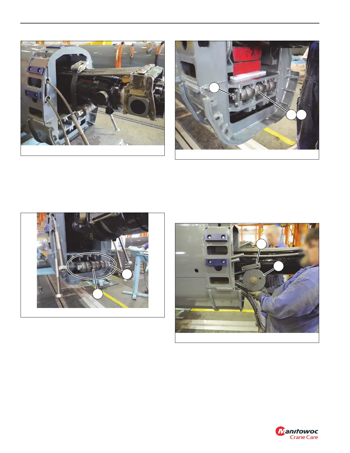
51. With shaft (117) holding the anchor ends of the six tele 3
extend cables (139) recessed into its keeper on tele 3
(4), secure shaft in place using two keeper plates (118),
four capscrews (56), four lockwashers (120), and four
flat washers (119) (see Figure 4-67).
52. Attach wear pads (53) to sheave mount weldments (112)
using four capscrews (123).
53. At rear of tele 3 (4), wrap tele 3 retract cable (114)
around sheave weldment (81), then install sheave
weldment (81) and thrust washers (83) on to shaft of
sheave mount weldment (112) (left and right sides).
Install grease fitting (109) on to shaft of sheave mount
weldment (112) (left and right sides) (see Figure 4-68).
54. Install sheave assembly (112, 81) into rear of tele 3 (4)
and secure with eight capscrews (113) and flat washers
(16) (left and right sides) (Figure 4-68).
55. Lower rear of telescope cylinder (6).
56. Apply anti-seize to shaft (115), then install roller (90),
shaft (115), and five narrow washers (116) into rear of
tele 3 (4). Index shaft (115) so that it can be secured in
place using two capscrews (85) and flat washers (91)
(see Figure 4-69 and Figure 4-70).
FIGURE 4-67
8804-31
118
139117

 Loading...


