4-37
Published 3/26/2018, Control # 596-05
GRT8100 SERVICE MANUAL BOOM
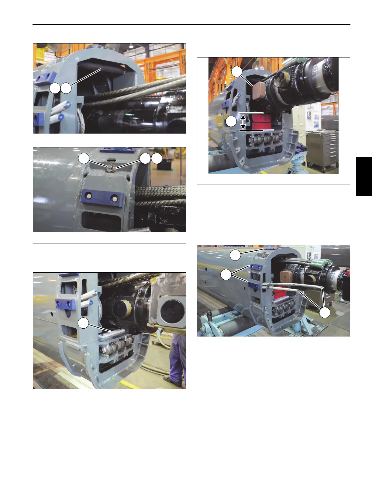
57. Lift rear of telescope cylinder (6), then install wear pad
(122) using two capscrews (31), lock washers (28, and
flat washers (27) (see Figure 4-71).
58. Remove the special tool (p/n MT102678) from the top of
the tele cylinder holding the 6 cables.
59. Lower cylinder on to blocks of wood measuring 7 in. in
height (L) (see Figure 4-72).
60. Apply anti-seize to trunnions at rear of telescope
cylinder (6). Install trunnion blocks (4x-148). Apply anti-
seize to trunnion blocks (left and right sides) (see
Figure 4-72).
61. Install threaded rods (10 mm-1.5 x 2 ft.) (M) in to ends of
the four tele 4 extend cables (104, 105) to aid in the
installation into tele 2 (3) (see Figure 4-73).
62. Mount wear pad (2x-53) to rear of tele 3 (4) using two
capscrews (56). Mount wear pads (4x-54) to rear of tele
3 (4) using two capscrews (56) (see Figure 4-73).
NOTE: When installing tele 3 (4) into tele 2 (3), add equal
number of shims (55) underneath wear pads (53,
54) such that the wear pads are within 2 mm of the
bottom and sides of tele 2 (3).
FIGURE 4-70
8804-29
115 9185

 Loading...


