Grove Published 10-01-2020 Control # 699-00 4-5
GRT9165 SERVICE MANUAL BOOM
a. Remove the right rear valve maintenance cover.
b. Remove capscrews (1, Figure 4-5) and bushings (2)
from the pivot pin.
c. Remove the nuts from the end of the push rods.
Install the pin removal tool (3) in the capscrew
holes. Thread the rods into the capscrew holes.
d. Connect hydraulic hoses (4 and 5).
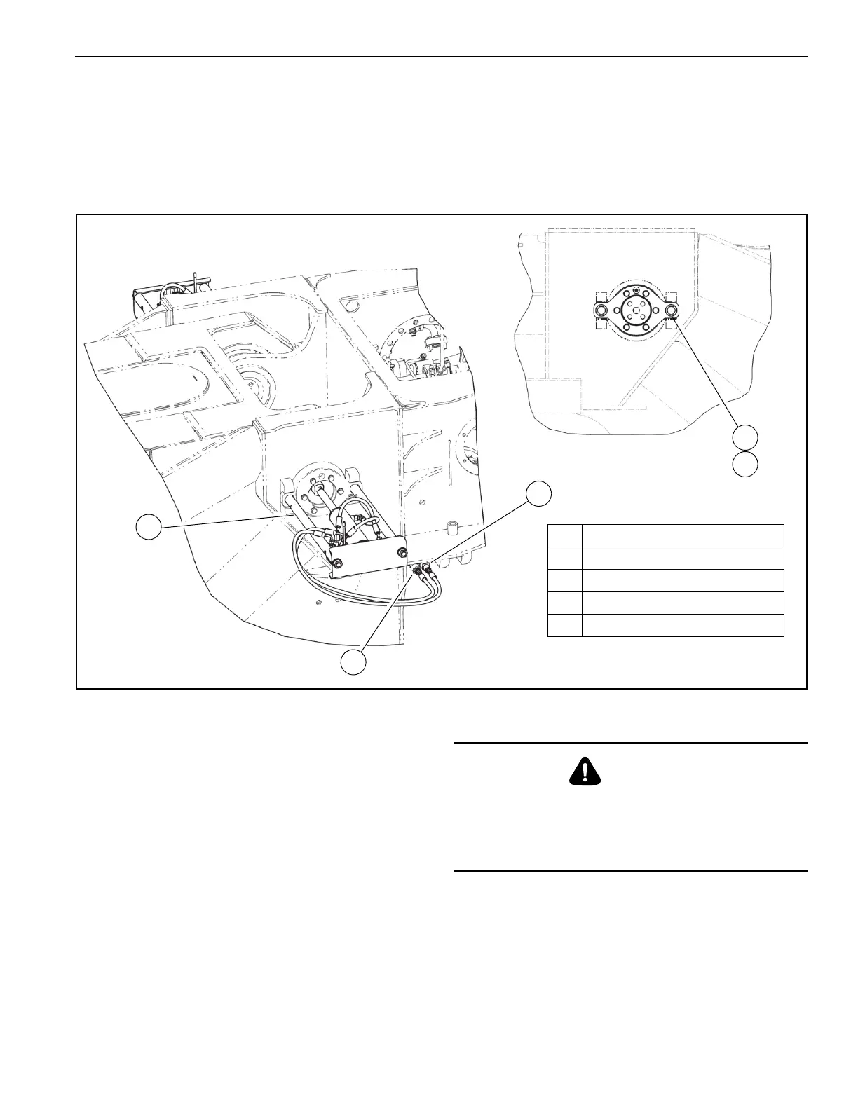
18. Install the boom pin removal tool (3, Figure 4-6) to the
left (cab) side of the superstructure as follows:
a. Deploy the maintenance platform as necessary. For
more information, see the Operator Manual.
b. Remove capscrews (1) and bushings (2) from the
pin.
c. Remove the nuts from the ends of the push rods.
Install the boom pin removal tool (3) in the capscrew
holes. Thread the rods into the capscrew holes.
NOTE: The hydraulic ports for the pin removal tool have
red caps.
d. Connect the hydraulic hoses (4 and 5).
19. Start the engine.
20. If necessary, verify that the hydraulic pin removal tools
are operational In the ODM. For more information, see
the “Boom Removal/Installation Function” section in the
Operator Manual.
21. For the right side pin, move the control handle (1,
Figure 4-7) on the removal tool to retract the pin.
22. For the left (cab) side pin, move the control hand (1) on
the removal tool to retract the pin.
10242
FIGURE 4-6
1
2
3
4
5
1 Capscrew M20 x 55 LG
2 Bushing
3 Boom Pivot Pin Removal Tool
4 Hydraulic Hose Connection
5 Hydraulic Hose Connection
10243
WARNING
Crushing Hazard!
Make sure the lifting device is capable of supporting the
boom assembly.
Severe injury or death may result.

 Loading...


