UNDERCARRIAGE GRT9165 SERVICE MANUAL
8-10
Published 10-01-2020 Control # 699-00
Removal
1. Thoroughly clean the steering control valve and the
surrounding area before removing the hydraulic hoses
from the valve.
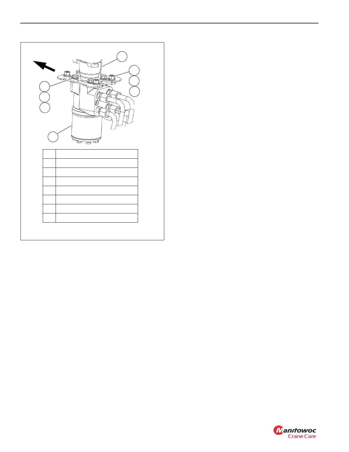
2. Tag and disconnect the hydraulic hoses from the
steering control valve (2, Figure 8-8). Cap or plug each
hose and the ports of the valve.
3. Remove hex nuts (3), lockwashers (4), and washers (5).
4. Remove the capscrews (6), lockwashers (7), and
washers (8) securing the valve (2) to the bracket and the
steering column (1). Remove the control valve, leaving
the steering column in the cab.
Installation
1. Position the control valve to the bracket and steering
column(1) and install the flatwashers (8), lockwashers
(7), and capscrews (6). Torque capscrews; refer to
Fasteners and Torque Values, page 1-16 for proper
torque.
2. Install washers (5), lockwashers (4), and hex nuts (3).
3. Connect the hydraulic hoses to the control valve (2) as
tagged during removal.
4. Start the engine and check for proper operation and any
leakage.
1
2
4
3
5
7
6
8
1 Steering Column
2 Steering Control Valve
3 Hex Nut 3/8-16 UNC SAE-2
4 Lockwasher
5 Flat Washer
6 Capscrew 3/8-16 UNC G5
7 Lockwasher
8 Flat Washer
FIGURE 8-8
Forward
10228

 Loading...


