8-27
GRT9165 SERVICE MANUAL UNDERCARRIAGE
Published 10-01-2020 Control # 699-00
11. Pull the outrigger beam out of the outrigger box, re-
adjusting the lifting attachment to prevent the extension
cylinder from sliding out of the outrigger beam when the
beam clears the outrigger box.
12. Position outrigger beam on blocking material.
Inspection
Inspect outrigger beams for bends, evidence of cracks, or
other damage. Check outrigger beam internally for hydraulic
fluid, which may indicate a leaking cylinder, loose
connection, or damaged hydraulic line.
Installation
1. If removed, install wear pads (16) into bottom inside of
outrigger box using plates (15) and jam nuts (14). Apply
anti-seize compound to the wear pads (16).
2. If removed, install wear pads (19) and plates (18) to the
top of the outrigger beam using capscrews (17). Apply
anti-seize to the wear pads (19).
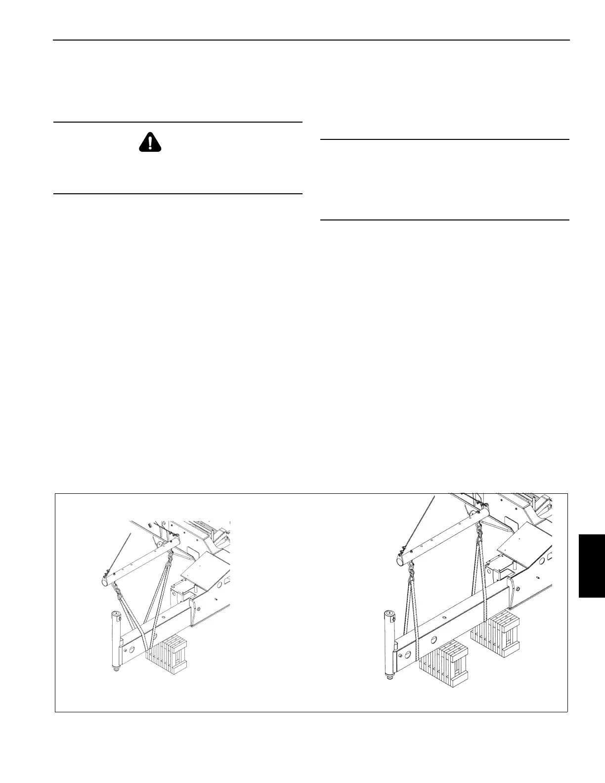
3. Attach an adequate lifting device of straps or belts to the
beam. Do not use chains, as they may nick the bottom
edges of the outrigger beam (see Figure 8-27).
NOTE: Outrigger beam assembly, with jack cylinder,
weighs approximately 984 kg (2169 lb).
4. Slide the beam into the outrigger housing and align the
cylinder bushing with the mounting hole. Be sure jack
cylinder hydraulic hoses do not get trapped against the
outrigger box during insertion.
5. Apply anti-seeze compound to the clevis pin (22,
Figure 8-26). Secure the cylinder barrel to the housing
with the clevis pin (22) and cotter pins (21).
6. Connect the hydraulic lines (20) as tagged during
removal. Connect the OMS electrical cable as tagged
during removal.
7. Fully extend and retract the outrigger beam, ensuring
the beam assembly rides on the top and bottom wear
pads.
8. Install outrigger end cover (13) with remove capscrews
(3), lockwashers (4), and washers (5).
9. Install lower outrigger cover (12) with washers (5),
lockwashers (4), capscrews (3), and retaining nuts (11).
10. If necessary, install grab handles (6) on ladder (10) with
capscrews (7), washers (8), and spacers (9).
11. If necessary, install grab handles (6) to upper cover (13)
with capscrews (3), lockwashers (4), and washers (5).
12. Install the outrigger boxes. For more information, see
the Operator Manual.
13. If extension cylinder was replaced, recalibrate the
outriggers.
DANGER
Be sure any blocking material used is capable of
supporting outrigger beam weight. Do not allow it to tilt or
slide.
CAUTION
Be sure that the piston side of all outrigger cylinders are
connected to the solenoid valve bank. Reversal of port
connection of the rod and piston sides could result in
severe damage to the cylinders as very high pressure
intensification will occur.
FIGURE 8-27
Rear Outriggers Shown
For reference only

 Loading...


