Installation and Operation Manual
10
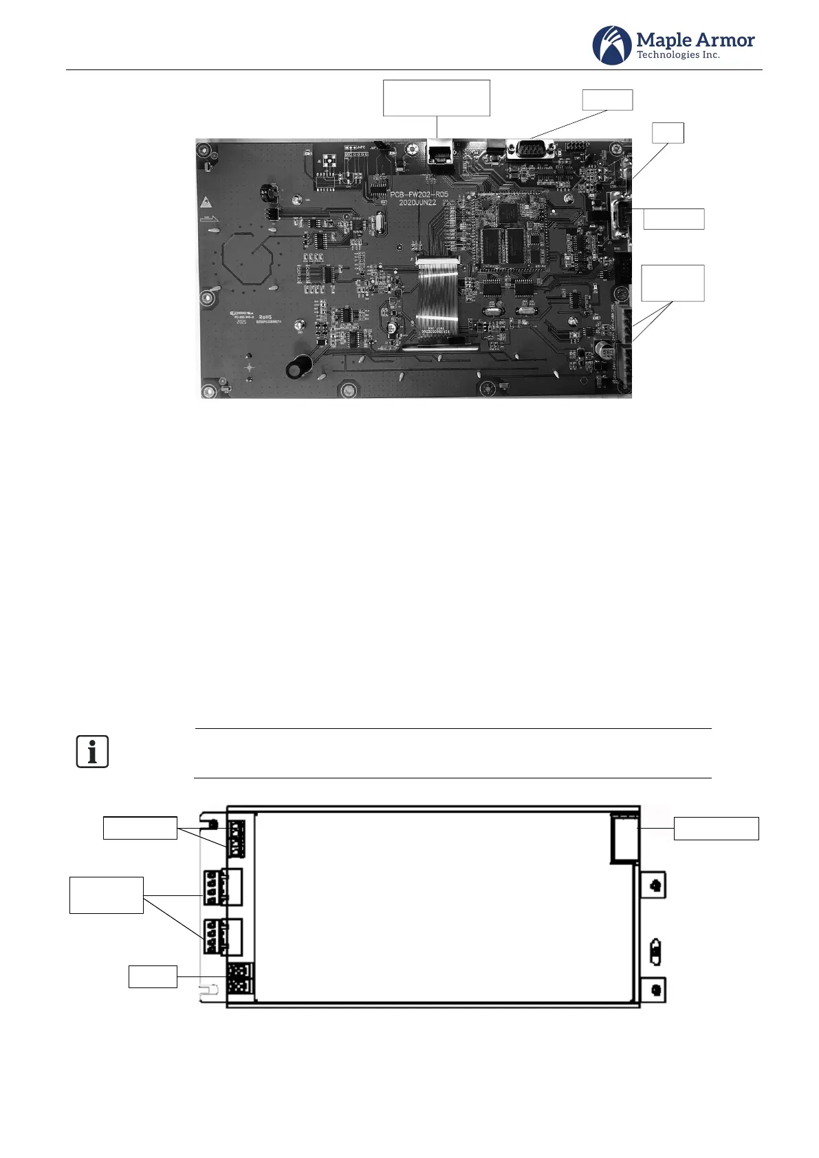
Ethernet Port
(for programming)
24V &
CAN bus
RS232
USB
RS232
Figure 5 AMI (Back)
PSU (Power Supply Unit)
112-120VAC, or 220-240VAC input selectable
Provide power supply output to the system
Terminals BAT+ and BAT- connect two lead-acid batteries (12VDC) in series.
Maximum Charge Voltage: 27.8 VDC
Maximum Charge Current: 2.5A. Sufficient battery charging capability is available to charge 40AH sealed
lead-acid batteries within code requirements for up to 24 hours standby plus 30 minutes alarm plus 5
minutes alert.
Use a microprocessor-controlled transfer circuit to switch power supply for the system to standby batteries
when AC power is off or low.
Communicate to the AMI to report fault conditions.
110-120VAC or 220-240VAC input is optional. A slide switch is used to fulfill this
function. Please refer to Power Supply Wiring section for switch usage information.
Battery
24V input
and CAN bus
Aux Outputs
AC input
Figure 6 PSU (Power Supply Unit)