Installation and Operation Manual
16
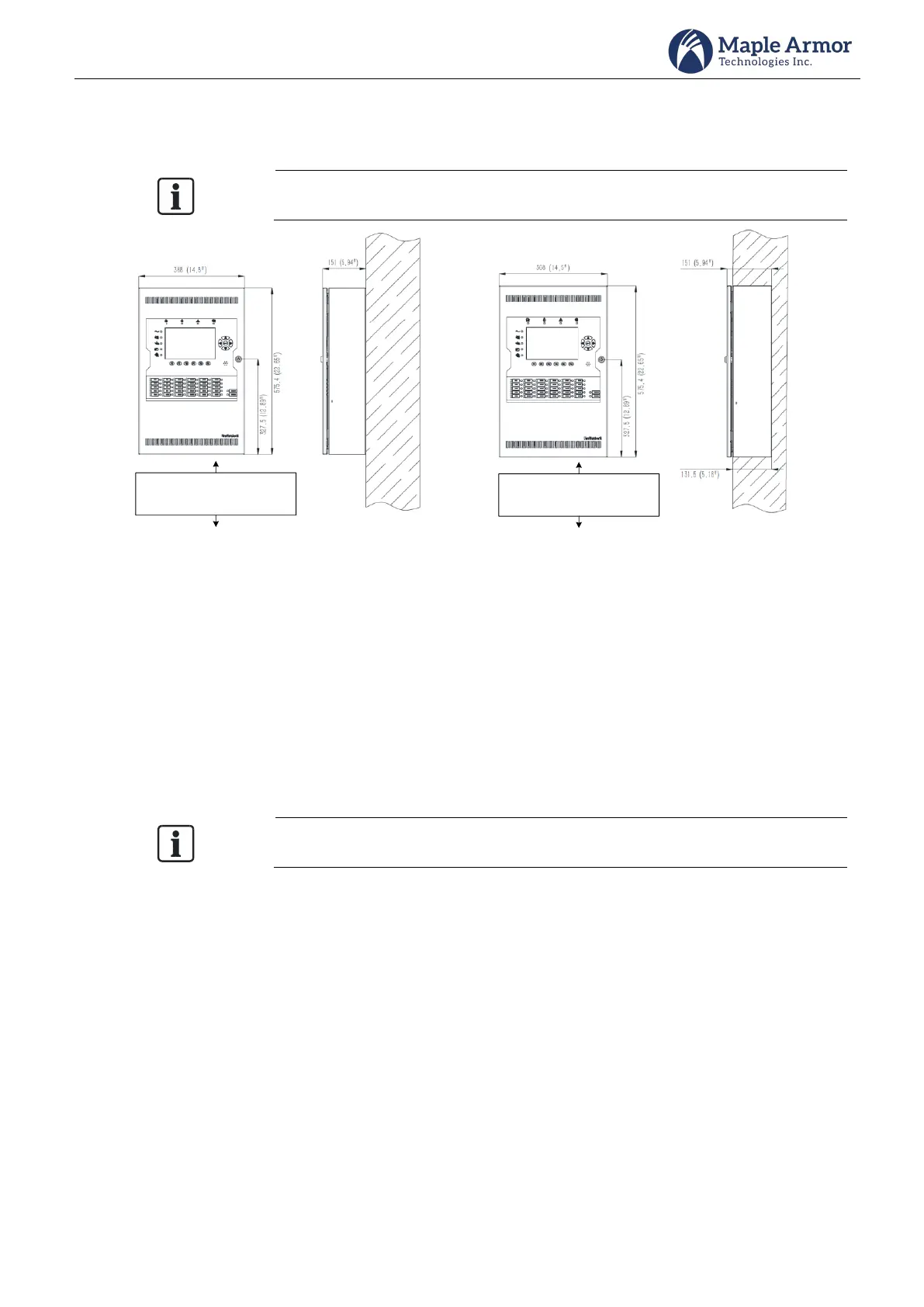
FW105 Mounting Space
The FW105 cabinet can be surface-mounted or flush-mounted.
Do NOT flush mount in a wall designated as a fire separation.
Mount Control Unit of convenient
height for access to display and
controls
Mount Control Unit of convenient
height for access to display and
controls
(a) Surface-mounted (b) Flush-mounted
Figure 12 FW105 Enclosure Mounting Size
FW105 Mounting Steps
Step 1. Drill the holes
Before installing any electrical components, drill the holes as follows.
Drill the hole on the position shown in Figure 13. The size of the holes shall be suitable for 1/2’ or 3/4’
conduit connection.
Remove shavings and smooth sharp edges. The hole must be round and smooth
Route all high voltage and non-power limited wiring away from power limited wiring.
Refer to the Power Limiting section for more details.