Installation and Operation Manual
29
Relay Output Circuit Wiring
MPU
1NO
1COM
1NC
3NO
3COM
3NC
2NO
2COM
2NC
4NO
4COM
4NC
Alarm
Relay
Trouble
Relay
Monitor
Relay
Superviso
ry Relay
Relay contact
(Shown in normal standby condition, see
left drawing)
NO – Normal Open
COM – Common
NC – Normal Close
Figure 32 Relay Output Circuit Wiring
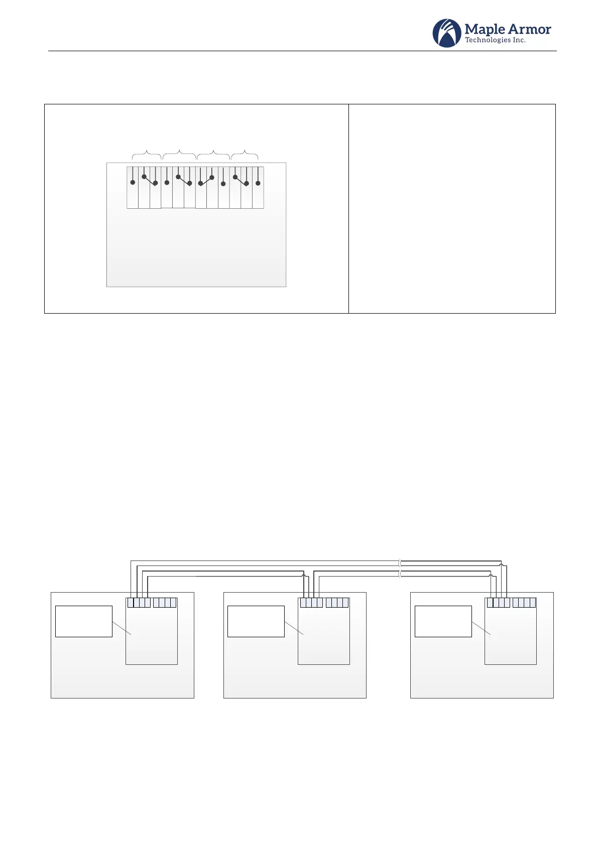
Network Circuit Wiring
Network can alternately connect up to 32 panels in Class X/DCLC wiring, and additional remote annunciators in
Class B/DCLB wiring. Total number of panels and annunciators is limited to 110.
Remote Device Power – The control panel auxiliary power can provide power for 3 annunciators. Each
address on the circuit must be fully powered from either auxiliary power of control panel UL/ULC Listed
power supply for use in fire alarm systems.
When connecting panels/annunciators on the external network circuit, the data wires must be daisy chained
and with no T-taps to preserve the integrity of the data. The following diagrams show the proper wiring.
Network Circuit Wiring – Class X/DCLC
Control Panel
Address =
1~32
CAN3L
CAN3H
CAN2L
CAN2H
CAN1L
CAN1H
CAN1L
CAN1H
Control Panel
Address =
1~32
CAN3L
CAN3H
CAN2L
CAN2H
CAN1L
CAN1H
CAN1L
CAN1H
Control Panel
Address =
1~32
CAN3L
CAN3H
CAN2L
CAN2H
CAN1L
CAN1H
CAN1L
CAN1H
Figure 33 External Network Circuit Wiring – Class X/DCLC