Installation and Operation Manual
11
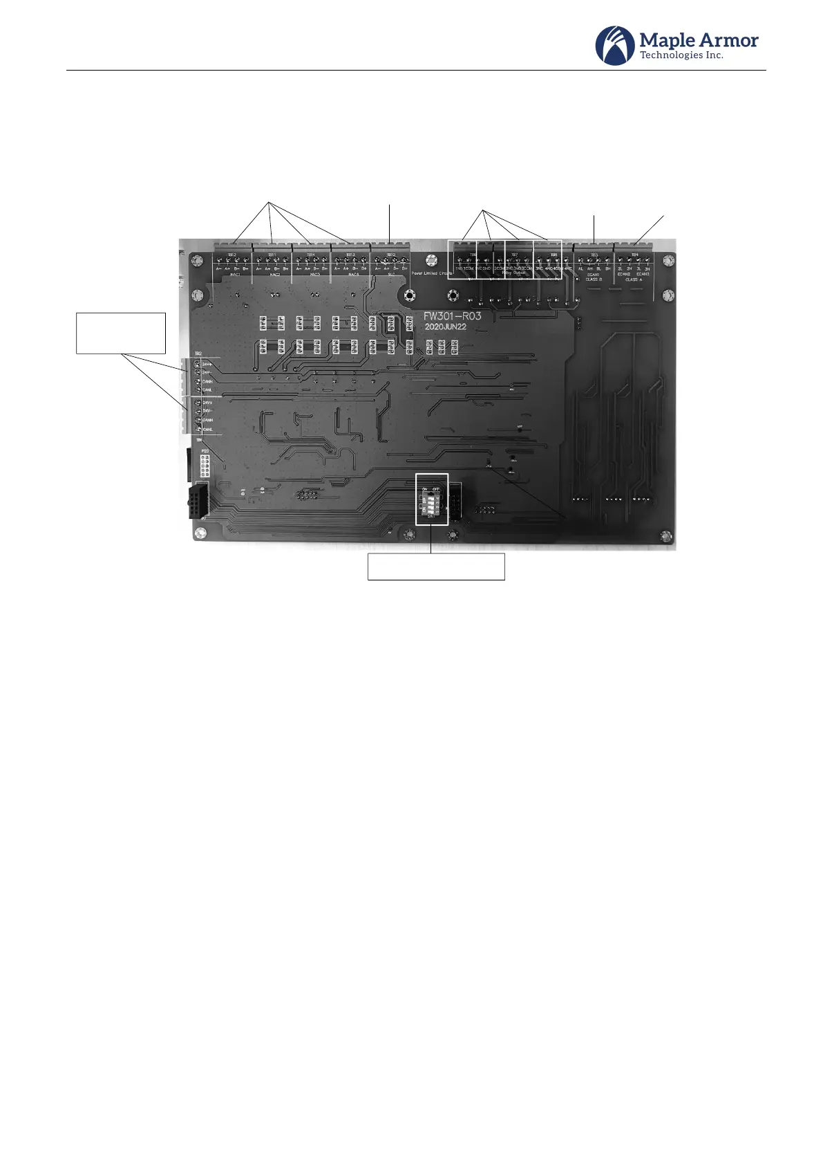
MFU (Multi-functional Unit)
MFU is a multi-functional unit that includes 4 NACs, 1 SLC, 4 Relays Outputs, and 2 network circuits. It is a fixed
unit for FW105.
24V input
and CAN bus
ISU setting switch
Network
(class X)
Network
(class B)
Relay Outputs
SLC
NACs
Figure 7 MFU (Multi-functional Unit)
Caution: Set correctly on ISU setting switch for proper operation
Switch terminal 1 and terminal 2 to ON position, and switch terminal 3 and terminal 4 to OFF position when ISU
is installed on the left slot.
Switch terminal 1 and terminal 2 to OFF position, and switch terminal 3 and terminal 4 to ON position when ISU
is installed on the right slot.
Switch terminal 1, terminal 2, terminal 3 and terminal 4 to ON position when no ISU is installed.
Switch terminal 1, terminal 2, terminal 3 and terminal 4 to OFF position when two ISUs are installed.
1) NAC (Notification Appliance Circuit)
MFU contains four independent notification appliance circuits.
Circuit topology support: Class A or Class B.
Maximum current: 2A per NAC, 10A maximum for all NACs (4 NACs on MFU + 4 NACs on NOU)
2) SLC (Signaling Line Circuit)
MFU contains one SLC supports up to 252 points of addressable devices.
Initializes and operates all devices residing on the loop and communicates all relevant devices and
event information, such as alarms and troubles, to the System CPU.
Circuit topology support: Class A/DCLA or Class B/DCLB.
Maximum current: 100 mA in Normal Standby, 220 mA in Alarm