Installation and Operation Manual
17
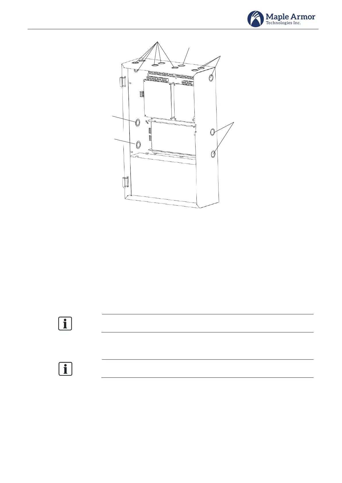
Power Limited
Non-Power
Limited
(for AC input)
Power Limited
Non-Power
Limited or high
voltage
(relay contact
wiring)
Power Limited
Non-Power
Limited
(for battery
wiring)
Figure 13 Hole Position
Step 2. Backbox Mounting
To install the backbox:
Select a clean, dry, shock, and vibration-free surface in a protected environment.
Position the cabinet clear of obstructions so that the front door opens freely and the controls and
indicators are easily accessible.
Mark the locations of the two upper mounting bolts of the cabinet on the wall. See Figure 14 for the
mounting size.
There are two key-shaped cutouts on the top of the back box. Make sure the end with
the two key-shaped cutouts is on top when installing the back box.
Drill the two holes marked in the previous step and screw in the top bolts, leaving a small gap between
the wall and each top bolt.
Choose a screw type and length able to support the control panel, options, and battery
set. You may need a different screw type depending on the wall material.
Place the cabinet over the two top bolts and allow it to slide down over the bolts.
Mark, drill, and install the two bottom bolts in the cabinet.
Tighten all four bolts securely against the back wall of the cabinet.