Installation and Operation Manual
30
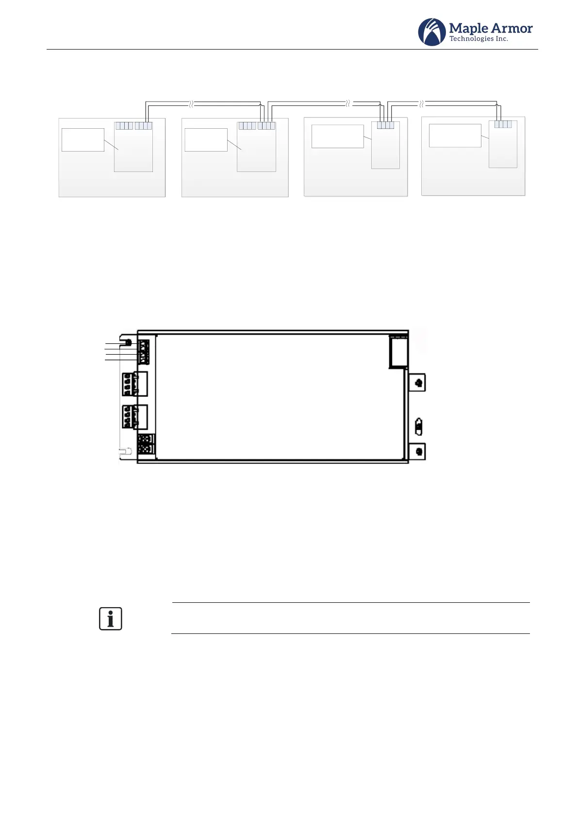
Network Circuit Wiring - Class B/DCLB
Control Panel
Address =
1~110
CAN3L
CAN3H
CAN2L
CAN2H
CAN1L
CAN1H
CAN1L
CAN1H
Control Panel
Address =
1~110
CAN3L
CAN3H
CAN2L
CAN2H
CAN1L
CAN1H
CAN1L
CAN1H
Annunciator
Address
=1~110
AL
AH
BL
BH
Annunciator
Address
=1~110
AL
AH
BL
BH
Figure 34 External Network Circuit Wiring - Class B/DCLB
Auxiliary Power Output Wiring
The Power Supply Unit provides two auxiliary power outputs. The power outputs can be configured as
resettable or non-resettable. The resettable terminal interrupts the power for 6 seconds after a reset condition.
Each circuit is limited to 1.0 A maximum.
510 mA in Normal Standby and 1.0 A in Alarm permitted in total for two aux power.
Figure 35 Auxiliary Power Output Wiring
Communication Port Connection
An Ethernet standard plug is provided for temporary connection to a computer for panel programming.
The Ethernet standard plug is connected to the Ethernet port of the computer that has the FW401 configurator
tool. This is used to upload and/or download panel configuration for programming.
The computer must be disconnected from the panel if not in use.