1. BulletSense can be configured in either station #4 or #5 (depending on whether you
are using a PowderSense).
Station 4: BulletFeeder dropper in Station 3 with standard crimp and seat dies.
Station 5: BulletFeeder dropper in Station 4. (using PowderSense® Powder check)
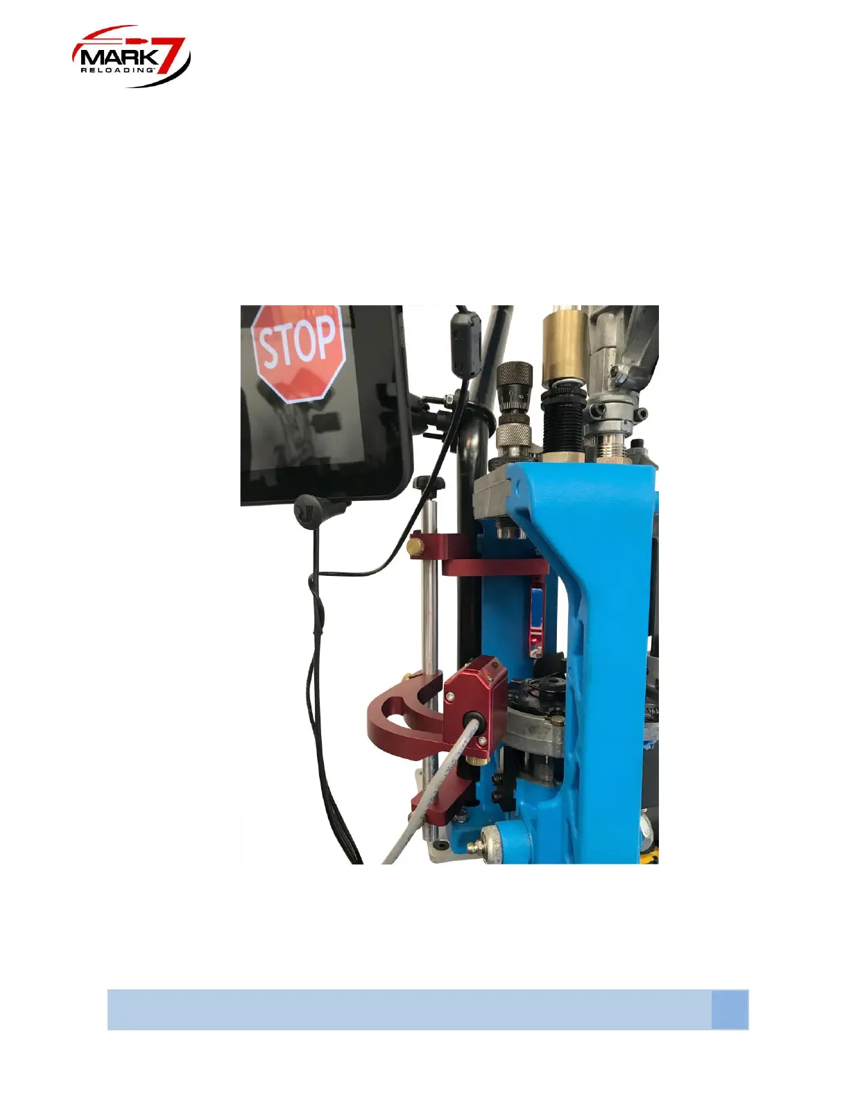
2. Once you decide which station, align the 650 BulletSense assembly with the mirror
holder by loosening the sensor head mount (middle arm) brass thumb screw and
rotating the sensor head to meet the mirror (see Figure 6).
Figure 40: Lining Up Laser with Mirror (Crude Adjustment)
3. Plug in the Sensor into Port #3 and power on the console which will automatically turn
on the laser. When you first power on the sensor look at the mirror to see where the