laser beam is directed. Use a thick white card/flat object to help find the exact position if
it’s difficult to detect the position.
**Please do not look directly into laser beam or directly at reflection in mirror**
WARNING – Class 3R laser: Avoid eye contact at all times; do not look directly
into the laser when adjusting the laser alignment.
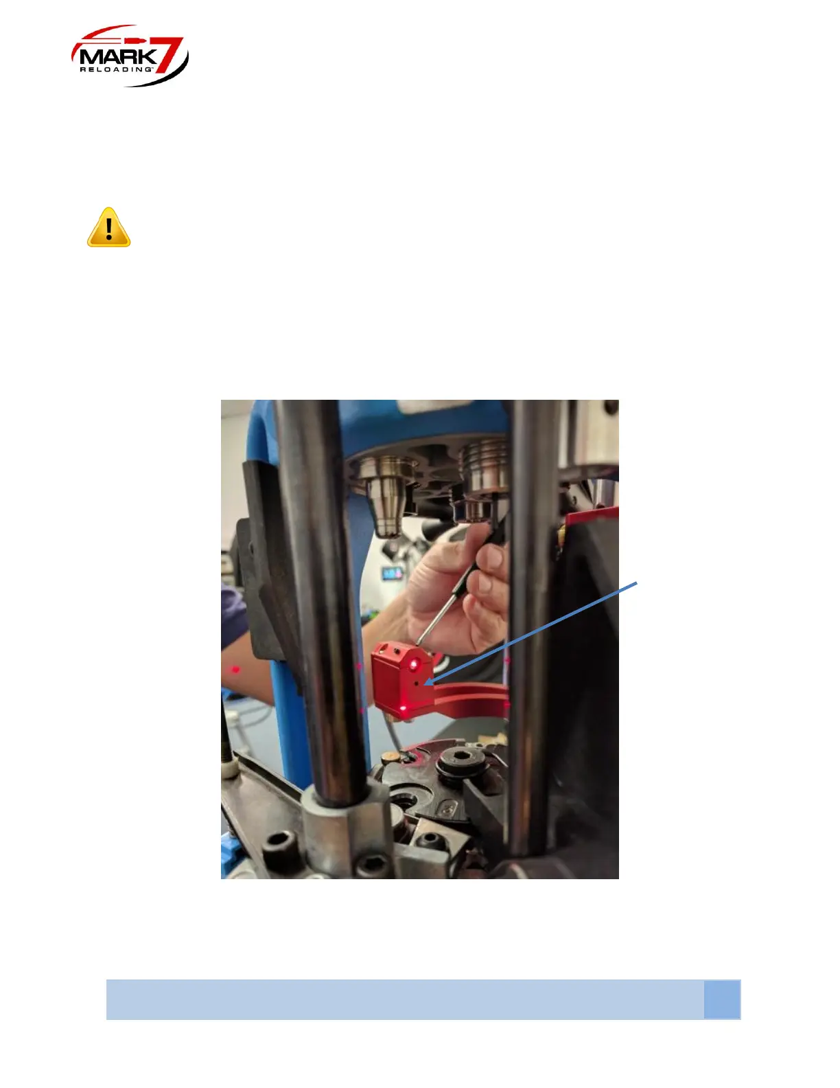
4. Adjust Laser beam onto the mirror with the 2X 6-32” set screws on the top of the
assembly with a Torx screwdriver size T6 x 40mm. Once the Laser diode is hitting the
mirror surface rotate the mirror using a 3/8” wrench so the laser beam is reflected back
to the sensor main body. Once the reflected laser beam appears on the sensor main
body, continue adjusting the set screws a little at a time to direct the laser beam into the
sensor hole as shown in Figure 7.
Figure 41: Adjusting Laser
5. Next the sensor vertical height must set for the given caliber and projectile being used.
This must be performed when the platform assembly is in the home position. Before