making the vertical adjustment perform a system calibration so the platform stops in the
home position.
6. To set the vertical adjustment, place a case with the neck expanded (pistol only) in
Station #4 or #5 and place a bullet in the proper orientation into the case at the level
where it would be when dropped from the Mr. Bulletfeeder drop tube.
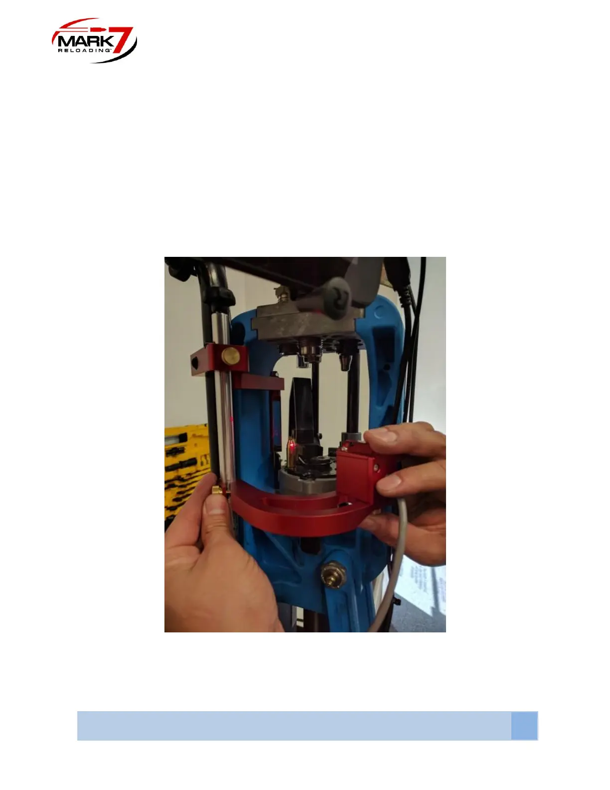
7. Loosen the brass thumb screw and gently position the sensor head mount (on middle
curved arm) so the laser beam goes OVER the tip of the bullet and hits the mirror, the
reflected beam should return and hit the tip of the bullet so the beam path is broken as
shown below (Figures 8 and 9). Once the height has been set, remove the bullet and
make sure the laser is still aimed at the sensor hole.
Figure 42: Setting Vertical height of laser