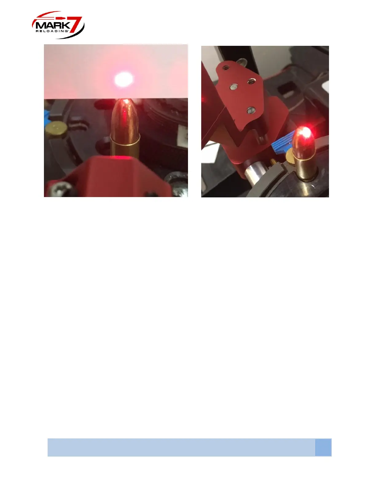
Figure 43: Beam Over Bullet (Left) the Reflected Beam Will Hit the Back of the Bullet (Right)
8. When the vertical height is correct a shadow will be cast on the sensor preventing the
sensor from “seeing” the laser beam. When the bullet is not present/upside down/
sideways the beam will pass over the bullet and contact the sensor triggering the
machine to stop.
9. It may be required to loosen the brass thumbscrew under the sensor head to add a slight
angle on the laser body to achieve a proper line of sight between the laser, bullet tip,
mirror and back to the sensor hole.
10. Once the proper height and adjustment has been achieved tighten the brass 2X thumb
screws located under the sensor head.
11. The sensor head assembly is designed to be rotated out of the way if you need to
access the shell plate or perform press maintenance. Use the plastic knob on top of the
rod to lift and rotate the sensor away from the machine.