3-44 Masterflex REGLO Digital Pump Drive with Advanced Connectivity
Section 4: Service & Maintenance
Masterflex
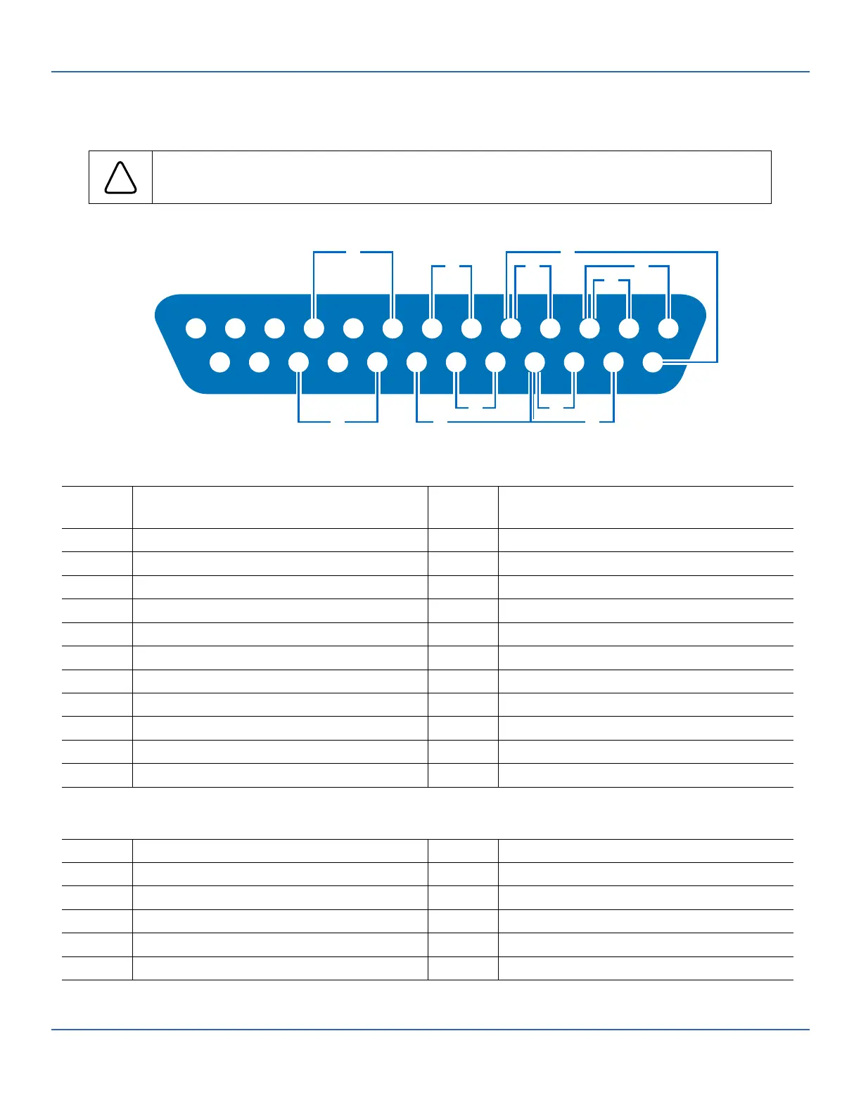
DB-25 ELECTRICAL CONNECTIONS
!
CAUTION: Power must be turned o before connecting the external analog control cable to
prevent damage to the drive.
Contact Arrangements:
Pin No.
DB-25
Description Pin No.
DB-25
Description
1 Speed Control Voltage Input (0–10 V) 14 Speed Signal Voltage Output (0–10 V)
2 Speed Control Current Input (0–20 mA) 15 Start/Stop Input
3 Speed Control Input Reference 16 CW/CCW Input
4 Speed Signal Current Output (0–20 mA) 17 Start/Stop, CW/CCW, Prime Reference
5 Speed Signal Output Reference 18 Tach Output Reference
6 Motor Running Relay Output (N.O.) 19 Tach Output (Open Collector)
7 Motor Running Relay Output Common 20 Prime Input
8 Open Head Sensor Relay Output (N.O.) 21 General Alarm Relay Output Common
9 Not Used 22 Not Used
10 Open Head Sensor Relay Output Common 23 General Alarm Relay Output (N.O.)
11–13 Not Used 24–25 Not Used
Wiring Scheme:
A Start/Stop G Tach Output
B CW/CCW H Prime
C Output (0–20 mA, 4–20 mA) I Motor Running (N.O.)
D Input (0–20 mA, 4–20 mA) J Open Head Sensor (N.O.)
E Input (0–10 V) K General Alarm
F Output (0–10 V)
13
12
11
10
9
8 7 6 5 4 3 2
1
25 24 23
22
21
20
19
18 17 16 15 14
F
HK
I E
A
G
D
C
B
J