106 CONTENTS
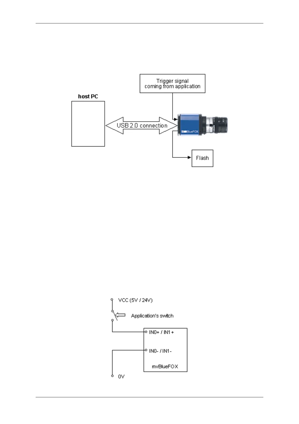
The camera is only connected by USB 2.0 cable to PC. All other signals are connected directly to the camera.
Trigger and flash signals are directly controlled by the FPGA, which does the timing in the camera. This makes the
trigger and flash control independent from CPU load of host PC or temporary USB 2.0 interrupts.
Figure 35: mvBlueFOX with trigger and flash
Trigger control
External trigger signal resets the image acquisition asynchronously to any other timing so that reaction delay is such
short that it can be ignored. If a delay between trigger signal and starting integration is needed, it can be defined.
By default it is set to 0 us.
Flash control
Signal for flash control is immediately set as soon as image integration begins. If a delay is needed it can be defined.
By default this delay is set to 0.
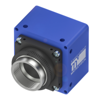
11.1.2.5.1 Connection
External trigger signal
Signal for triggering image acquisition must be connected to digital input on backside of mvBlueFOX on D-Sub
9-pin connector (p. 45). You can choose either input IN0 (pin 6 and 1) or IN1 (pin 9 and 4) for triggering.
MATRIX VISION GmbH