56 CONTENTS
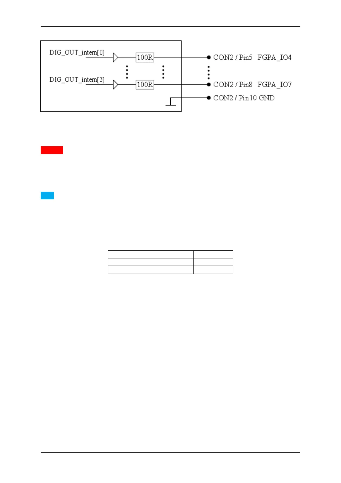
Figure 16: Digital output mvBlueFOX-Mxxx
Attention
The Dig I/O are connected directly via a resistor to the FPGA pins and therefore they are not protected. For
this reason, an application has to provide a protection circuit to the digital I/O of mvBlueFOX-M.
Note
The Dig I/O characteristics of the mvBlueFOX-M are not compatible to the Dig I/O of the mvBlueFOX standard
version.
8.3.2 LED states
State LED
Camera is not connected or defect LED off
Camera is connected and active Green light on
8.3.3 Components
• 8 Mpixels image memory
8.3.4 Accessories mvBlueFOX-Mxxx
8.3.4.1 mvBlueFOX-M-FC-S
The mvBF-M-FC-S contains high capacity condensers with switching electronics for transferring stored energy of
the condensers to external flash LEDs. It is possible to connect 2 pushbuttons/switches to the 8-pin header (CON3
- Control connector). Additionally, 2 LED interfaces are available. There are two version of mvBF-M-FC-S:
• Model 1 can be connected to mvBlueFOX-M with a cable via CON5.
• Model 2 can be mounted on the mvBlueFOX-M via CON1 directly.
MATRIX VISION GmbH