68 CONTENTS
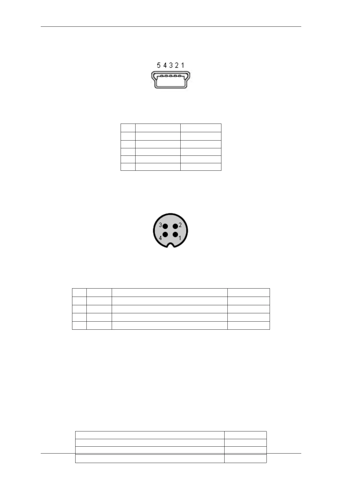
8.5.1.1 Mini-B USB (USB 2.0)
Figure 30: Mini-B USB
Pin Signal Comment
1 USBPOWER_IN Supply voltage
2 USB_DATA- Data
3 USB_DATA+ Data
4 ID Not connected
5 GND Ground
8.5.1.2 4-pin circular plug-in connector with lock (I/O)
Figure 31: 4-pin circular plug-in connector (female)
Pin Signal Comment Color (of cable)
1 IN0 + Opto-isolated digital input 0 (Positive voltage) brown
2 IN0 - Opto-isolated digital input 0 (Negative voltage) white
3 OUT0 + Opto-isolated digital output 0 (Positive voltage) blue
4 OUT0 - Opto-isolated digital output 0 (Negative voltage) black
Manufacturer: Binder
Part number: 79-3107-52-04
8.5.1.2.1 Electrical characteristic
Please have a look at the mvBlueFOX-MLC digital I/O characteristics (opto-isolated model) of the 12-pin Wire-to-
Board Header (USB / Dig I/O) (p. 59).
8.5.2 LED states
State LED
Camera is not connected or defect LED off
Camera is connected but not initialized or in "Power off" mode. Orange light on
Camera is connected and active Green light on
MATRIX VISION GmbH